Charge air cooler

a technology of air cooler and air intake, which is applied in the direction of indirect heat exchangers, machines/engines, lighting and heating apparatus, etc., can solve the problems of lack of air supply to the combustion engine, water in liquid form may freeze to become ice, etc., and achieve the effect of simple and reliabl

Inactive Publication Date: 2010-11-09
SCANIA CV AB
View PDF15 Cites 16 Cited by
  • Summary
  • Abstract
  • Description
  • Claims
  • Application Information

AI Technical Summary

Benefits of technology

[0005]The object of the present invention is to provide a charge air cooler so constructed as to make it possible to control the flow of compressed air through the charge air cooler in a simple and reliable manner so that a combustion engine can substantially always be supplied with compressed air which is at an optimum temperature.
[0006]This object is achieved with the charge air cooler of the invention. Using at least one control element which can be set in various positions makes it possible to control effectively and accurately the flow of compressed air through the tubular element of the air cooler. The flow of compressed air is proportional to the air flow velocity through the charge air cooler. The smaller the flow passing through the charge air cooler, the lower the flow velocity of compressed air through the charge air cooler. When the flow velocity through the charge air cooler is low, the compressed air undergoes effective cooling. Adjusting the flow of compressed air through the tubular element thus makes it possible to alter the efficiency of the charge air cooler so that the compressed air can be cooled to a temperature which more or less approximates to the temperature of the cooling medium. The temperature of the compressed air after cooling in the charge air cooler is nevertheless largely determined by the temperature of the cooling medium. The temperature of the cooling medium itself varies considerably in cases where it takes the form of surrounding air. The control element according to the present invention can thus be used for very exact control of the flow of compressed air through the tubular element of the charge air cooler. It is therefore also possible to give the compressed air led to the combustion engine a substantially optimum temperature irrespective of the temperature of the surrounding air and the operating state of the combustion engine.
[0007]According to an embodiment of the present invention, the control element can be set steplessly in various positions between a first extreme position whereby a maximum flow of compressed air is led to the flow duct and a second extreme position whereby a minimum flow of compressed air is led to the flow duct. The flow of compressed air can thus be adjusted very exactly by moving the control element to a suitable position along a path which comprises said extreme positions. The compressed air led from the charge air cooler to the combustion engine can thus be given a desired temperature with very good precision.
[0009]According to a preferred embodiment of the present invention, the charge air cooler comprises a tank adapted to receiving compressed air before or after the latter has been cooled in the tubular element, whereby the control element is arranged inside said tank. Most conventional charge air coolers are provided with a warm tank on one side of the tubular element for accumulating warm compressed air before it is cooled, and a cold tank on the opposite side of the tubular element for accumulating the cooled compressed air. The control element may be in a protected location inside one of these tanks, close to the inlet aperture or the outlet aperture of the tubular element. The control element is with advantage platformlike and movable in a two-way rectilinear direction. Such a control element occupies a relatively small amount of space in the charge air cooler. It is also relatively easy to provide the control element with two-way mobility along a rectilinear path, but it is possible to arrange the control element so that it is provided with some other type of movement. The charge air cooler may comprise an actuator adapted to moving the control element to desired positions. As the inlet the hole and the inlet aperture are normally of relatively small dimensions, the control element need only be moved a relatively short distance by the actuator in order to alter the flow of compressed air through the inlet passage or the outlet passage. The actuator may be a proportional valve, e.g. in the form of a solenoid. It may also be an electrically, hydraulically or pneumatically powered actuator of another kind. With advantage, the charge air cooler comprises a control unit adapted to controlling the activation of the actuator in such a way as to move the control element to desired positions. The control unit may be a computer unit with suitable software for controlling the control element. To make functional control of the control element possible, the control unit may receive suitably operation-related information such as the temperature of the compressed air led to the combustion engine, the temperature of the surrounding air or other relevant information.

Problems solved by technology

When the temperature of the surrounding air is very low, there is also risk that water in liquid form may freeze to become ice inside the charge air cooler.
This may cause operational malfunctions if the cooler freezes up, resulting in a lack of air supply to the combustion engine.

Method used


Image

  • Charge air cooler
  • Charge air cooler
  • Charge air cooler

Examples


Embodiment Construction

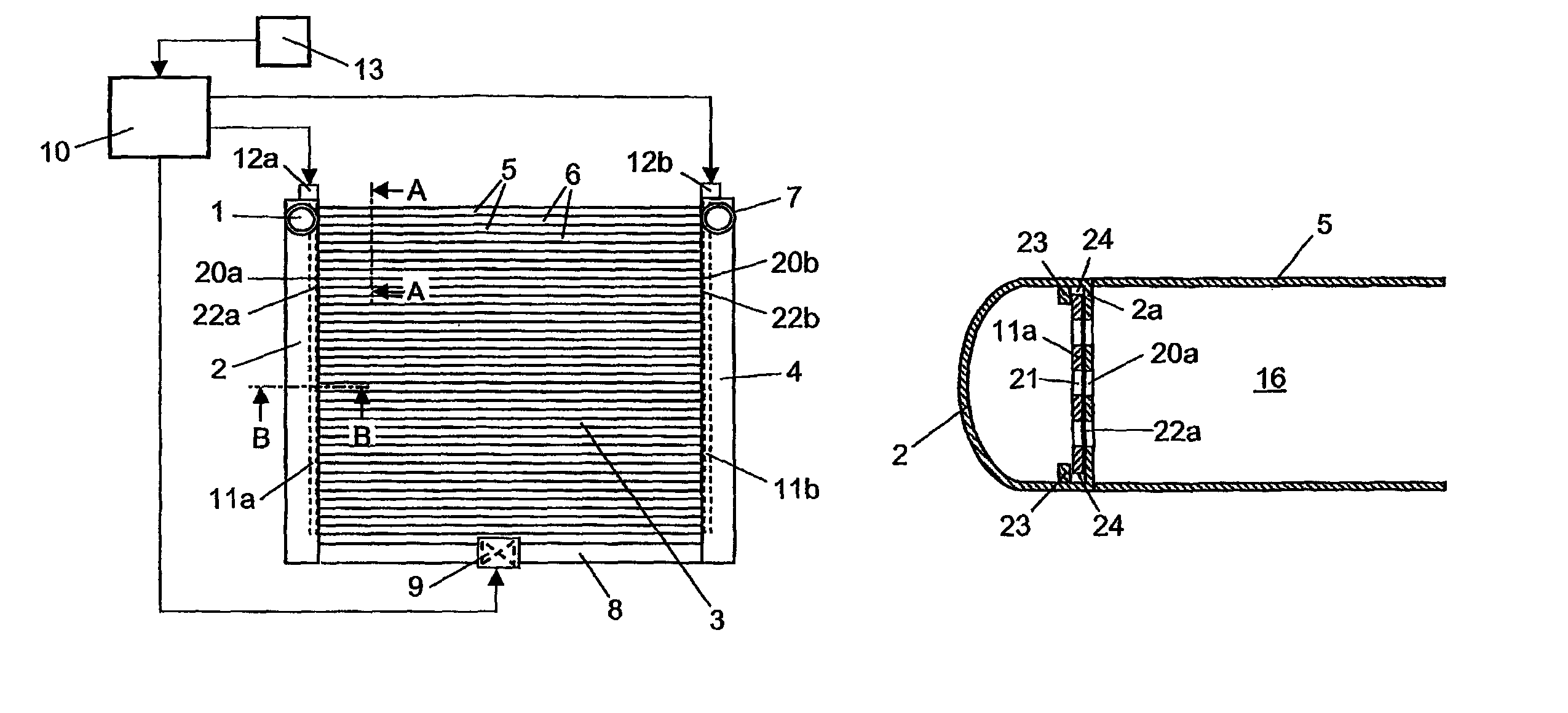
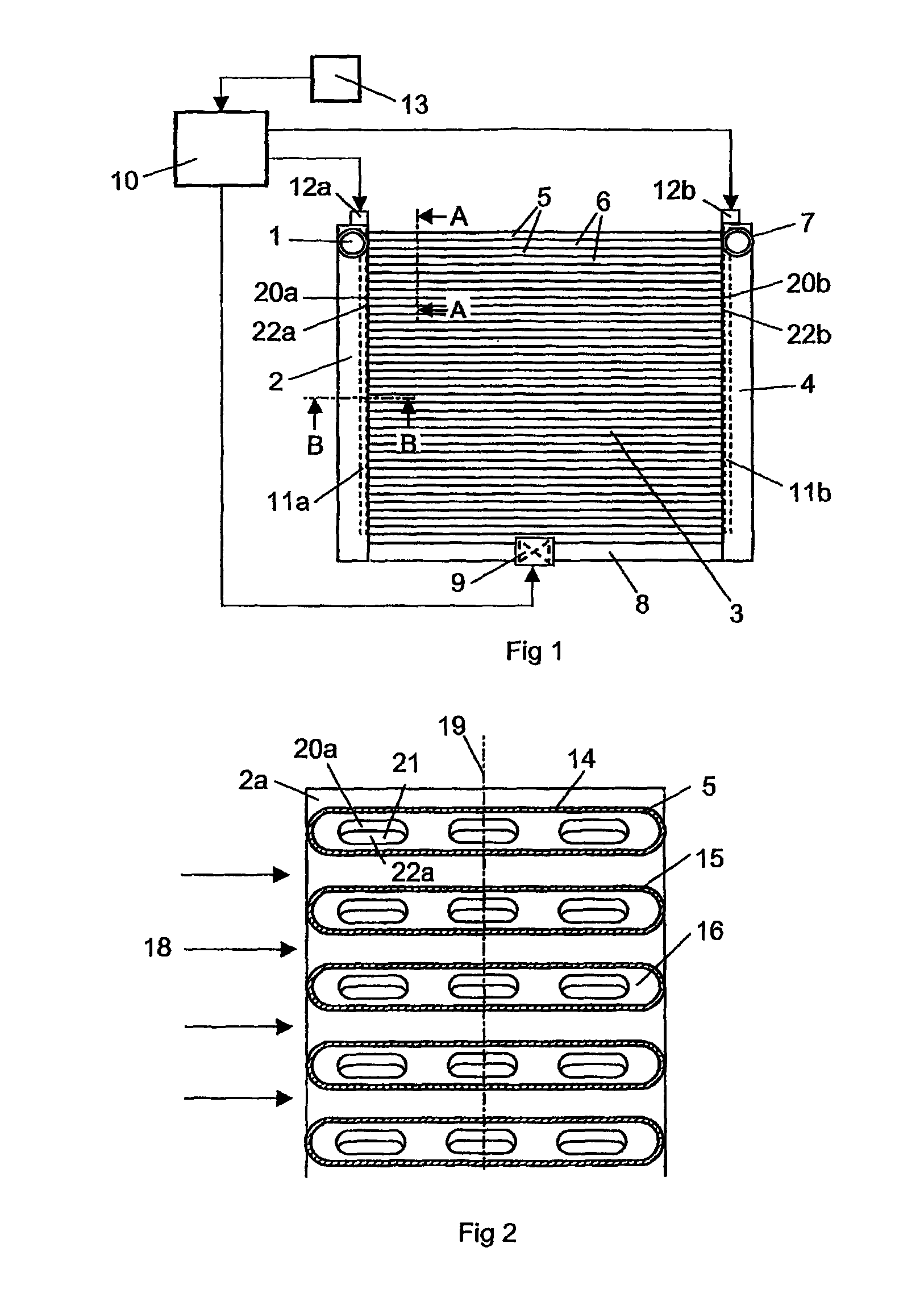
[0017]FIG. 1 depicts a charge air cooler which may for example be fitted at a front portion of a vehicle which is powered by a supercharged combustion engine. A supercharged combustion engine needs a supply of compressed air. The function of the charge air cooler is to cool the compressed air before it is led to the combustion engine. The charge air cooler comprises an inlet 1 to a first tank 2 which receives warm compressed air from a compressor. The charge air cooler comprises a cooler package 3 which extends between the first tank 2 and a second tank 4 for receiving cooled compressed air. The cooler package 3 comprises a plurality of tubular elements 5 which extend in a substantially rectilinear manner in a common plane between the first tank 2 and the second tank 4.

[0018]The tubular elements are arranged parallel at a substantially uniform distance from one another so that there are regular gaps 6 between adjacent tubular elements 5. Surrounding air can therefore flow through th...


PUM


Abstract

A charge air cooler comprising at least one tubular element with an internal flow duct for leading compressed air between an inlet aperture and an outlet aperture. A medium at a lower temperature than the compressed air is caused to flow in contact with an outside surface of the tubular element cooling the compressed air in the tubular element when the air is led through the flow duct. A movable control element is arranged close to the inlet aperture or the outlet aperture of the flow duct. A control for the control element provides a variable flow of compressed air through the flow duct as the movable control element is placed in various positions.

Description

CROSS REFERENCE TO RELATED APPLICATION[0001]The present application is a 35 U.S.C. §§371 national phase conversion of PCT / SE2006 / 000127, filed 30 Jan. 2006, which claims priority of Swedish Application No. 0500371-0, filed 17 Feb. 2005. The PCT International Application was published in the English language.BACKGROUND TO THE INVENTION, AND STATE OF THE ART[0002]The present invention relates to a charge air cooler for a supercharged combustion engine, and particularly to control over the flow of air to be cooled through the air cooler.[0003]The amount of air which can be supplied to a supercharged combustion engine of a vehicle depends on the pressure of the air but also on the temperature of the air. Supplying the largest possible amount of air to a supercharged combustion engine entails cooling compressed air in a charge air cooler before it is led to the combustion engine. The charge air cooler is usually situated in front of the conventional radiator of a vehicle. A charge air co...

Claims


Application Information

Patent Timeline
Patent Type & Authority Patents(United States)
IPC IPC(8): F28F27/02
CPCF02B29/0418F02B29/0456F02B29/0475F28D1/05366F28F27/02F02B29/0493F28F2250/06Y02T10/146Y02T10/12
Inventor HAGBERG, MAGNUSPETTERSSON, HENRIK
Owner SCANIA CV AB
Why Eureka
Try Eureka