
Crib mattress elevation system and control unit

a crib and control unit technology, applied in the field of cribs, can solve the problems of no control between these two positions, more likely that a baby could climb over the enclosure and fall out of the crib, and a long time-consuming process, so as to enhance the ability to monitor the baby, enhance the comfort and safety of the baby, and improve the convenience of the user of the crib

Inactive Publication Date: 2010-11-09
HOLMAN KATHLEEN ELIZABETH
View PDF26 Cites 34 Cited by
  • Summary
  • Abstract
  • Description
  • Claims
  • Application Information

AI Technical Summary

Benefits of technology

Enhances user convenience and safety by allowing precise adjustment of the mattress height, reducing strain on caregivers, improving baby safety by preventing falls, and providing remote monitoring and stimulation features.

Problems solved by technology

However, this is a fairly time consuming process and often it would be quicker and more convenient to avoid use of the crank.
Another drawback is that should the mattress be left at a higher position, for convenience, it makes it more likely that a baby could climb over the enclosure and fall out of the crib.
By design, this is a two position system and has the drawback that there is no control between these two positions.
Stopping at an intermediate position is not possible.
Another drawback with prior systems is that there is no coordination with the side panel.
While the side panel may be manually moved in some cases, the side panel movement is not integrated with a mattress elevation system.
Consequently, even with the mattress raised to a certain level, there is some difficulty in placing the baby in the crib, or taking the baby out of the crib.

Method used


Image

  • Crib mattress elevation system and control unit
  • Crib mattress elevation system and control unit
  • Crib mattress elevation system and control unit

Examples


Embodiment Construction

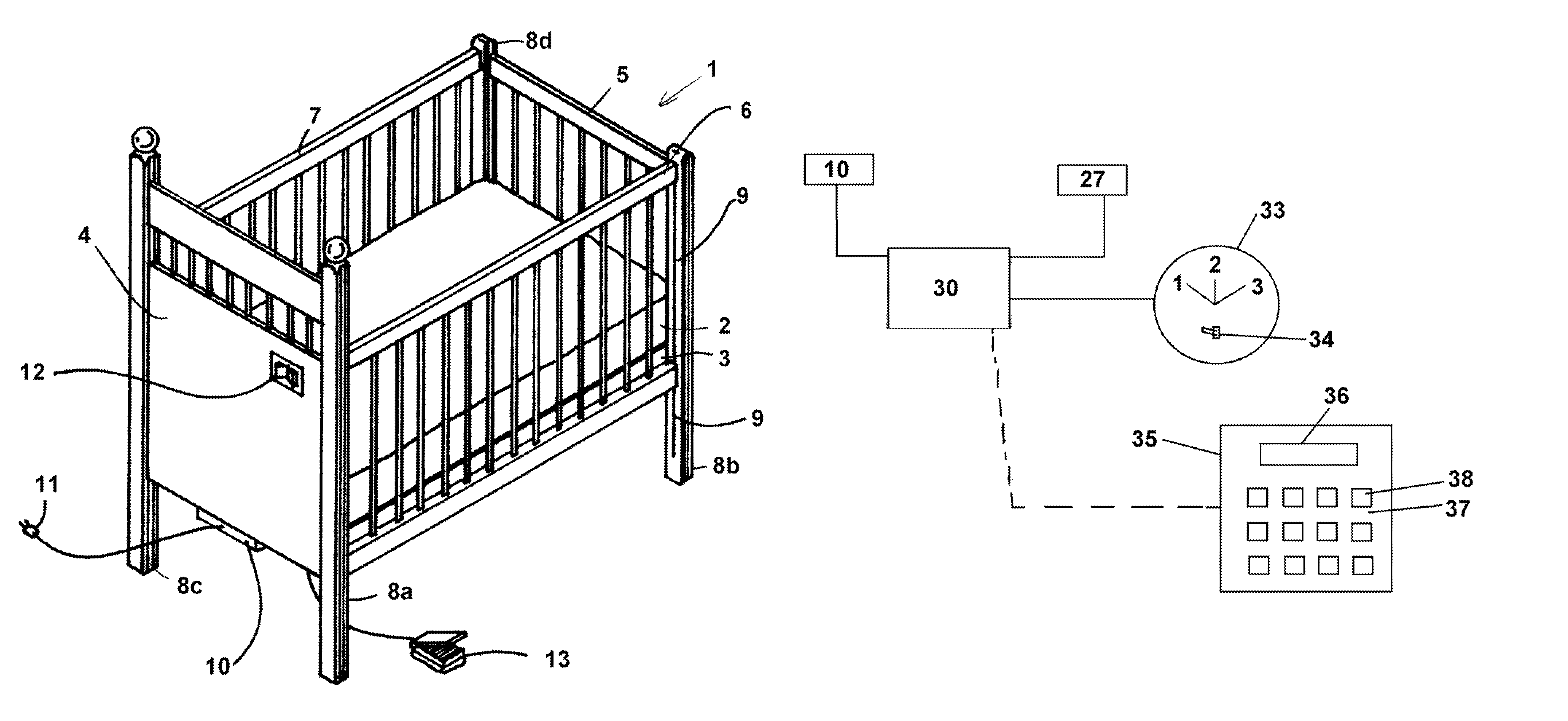
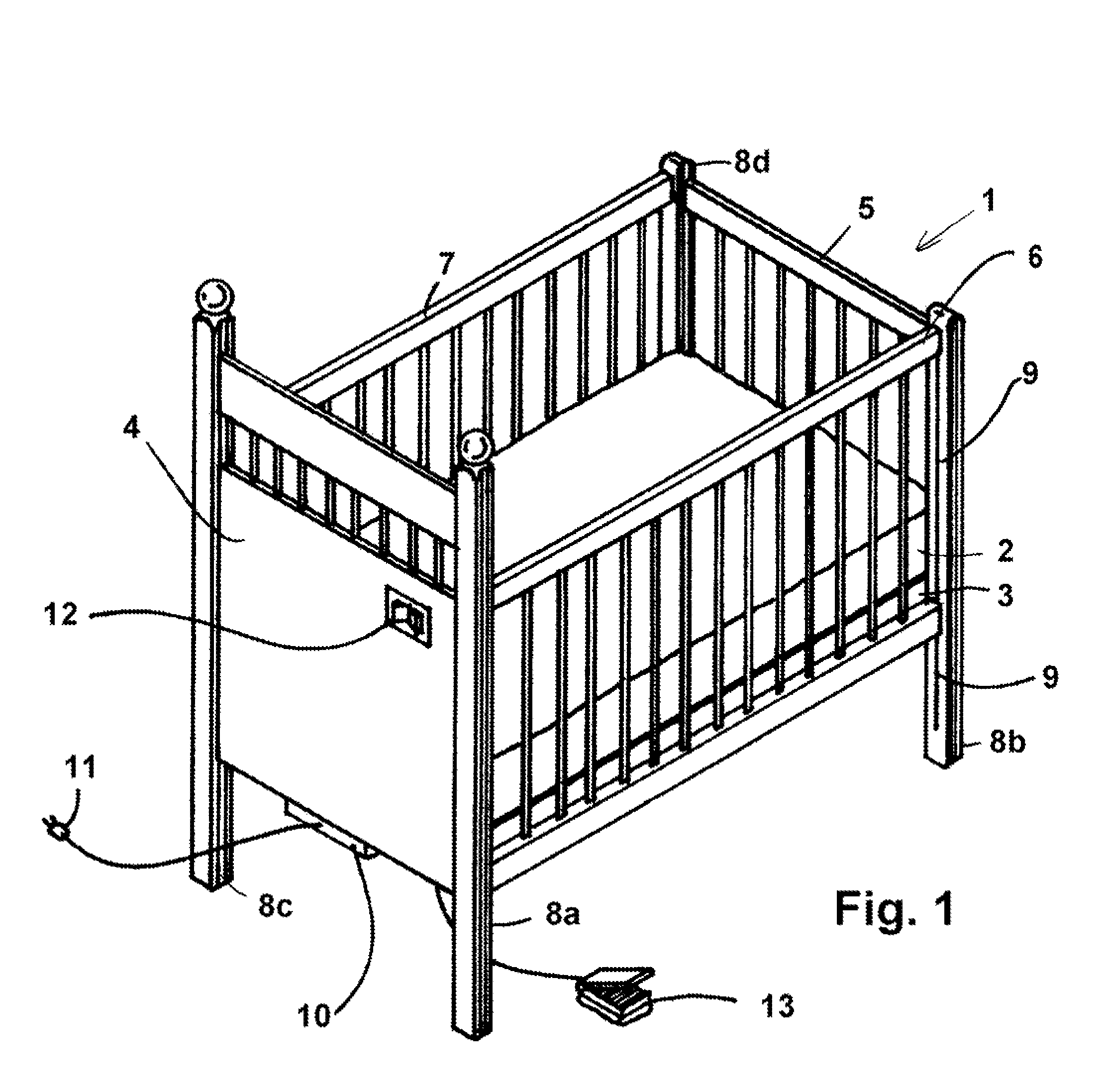
[0029]Referring to FIG. 1, a crib 1 has a mattress 2 supported on a frame 3. The frame 3 is integrated with a head panel 4, a foot panel 5 and a pair of side panels 6 and 7.

[0030]In this embodiment, which is a typical construction, the crib has four corner posts, 8a, 8b, 8c, 8d, the two front posts 8a and 8b having slide guide channels 9 for supporting the raising and lowering of the side panel 6. In this embodiment, an electric drive motor 10 is mounted beneath the frame, having a conventional power cord 11 for connecting to a power source. Two means of activation are shown, a intermittent push button switch 12 for raising or lowering the frame, depending on whether the switch is pushed to one side or the other, the center position being the normal off position, to which the switch automatically returns in the absence of finger pressure. A foot pedal operator 13 operates in the same way, with stepping on and off reversing the direction so as to provide hands free operation.

[0031]Re...


PUM


Abstract

A “smart crib” has a frame movably supported by posts, a mattress supported on the frame, the frame being movable between a raised position and a lowered position, a protective enclosure surrounding the frame and mattress, having at least one portion movable between a raised and a lowered position. The crib also includes a first elevation mechanism for moving the frame between the lowered position and the raised position, and a second elevation mechanism for moving the enclosure portion between the raised position and the lowered position. A controller is provided which is responsive to a user's inputs to selectively activate the first elevation mechanism, the second elevation mechanism or both mechanisms to move the frame with the bed and the movable enclosure portion to positions selected by the user between their respective raised and lowered positions, to ease not only placing a baby into the crib, but to also integrate other devices such as baby monitors, temperature and proximity sensors, and even to provide for remote computer access to check in and monitor baby activity.

Description

TECHNICAL FIELD[0001]This invention relates to baby cribs which have a mattress which may be raised or lowered automatically, preferably in coordination with the raising or lowering of a protective side panel to make it easier to place or remove a baby from the crib, and to a crib control unit which may optionally be incorporated with the crib.BACKGROUND[0002]Baby cribs are fairly well known to comprise a mattress that is fixed at a relatively low level within a protective enclosure, normally having a pair of side panels that may be manually raised or lowered. The distance between the mattress height and the top of the side panels is set high enough to limit a baby's ability to climb out of the crib.[0003]While offering good protection to most infants, this does require a person to awkwardly bend over the side panels to reach the baby, or to first drop the side panel to move the baby into or out of the crib. Even with the panel lowered, the mattress level is typically at a height wh...

Claims


Application Information

Patent Timeline
Patent Type & Authority Patents(United States)
IPC IPC(8): A47D7/02A47D7/03A47D13/06A47C21/08
CPCA47D7/03A47D9/012
Inventor HOLMAN, KATHLEEN ELIZABETH
Owner HOLMAN KATHLEEN ELIZABETH
Learn More