
Wireless multimedia system

a multimedia system and wireless technology, applied in the field of wireless distribution systems, can solve problems such as extraordinary bandwidth and channel capacity

Active Publication Date: 2010-11-02
BE LABS
View PDF28 Cites 67 Cited by
  • Summary
  • Abstract
  • Description
  • Claims
  • Application Information

AI Technical Summary

Benefits of technology

[0008]This invention relates to a wireless distribution system for home or business comprising a unitary distribution box, called a wireless multimedia center (WMC), which has inputs for receiving signals from one or more of: a satellite dish; a terrestrial antenna such as a VHF / UHF; a cable line; a telephone or data line such as ISDN, DSL, etc.; and / or fiber optic line, and any other future data or program sources can also be transparently input to the WMC with appropriate modifications or modular plug-ins.

Problems solved by technology

Special multiplexing techniques result in extraordinary bandwidth and channel capacity.

Method used


Image

  • Wireless multimedia system
  • Wireless multimedia system
  • Wireless multimedia system

Examples


Embodiment Construction

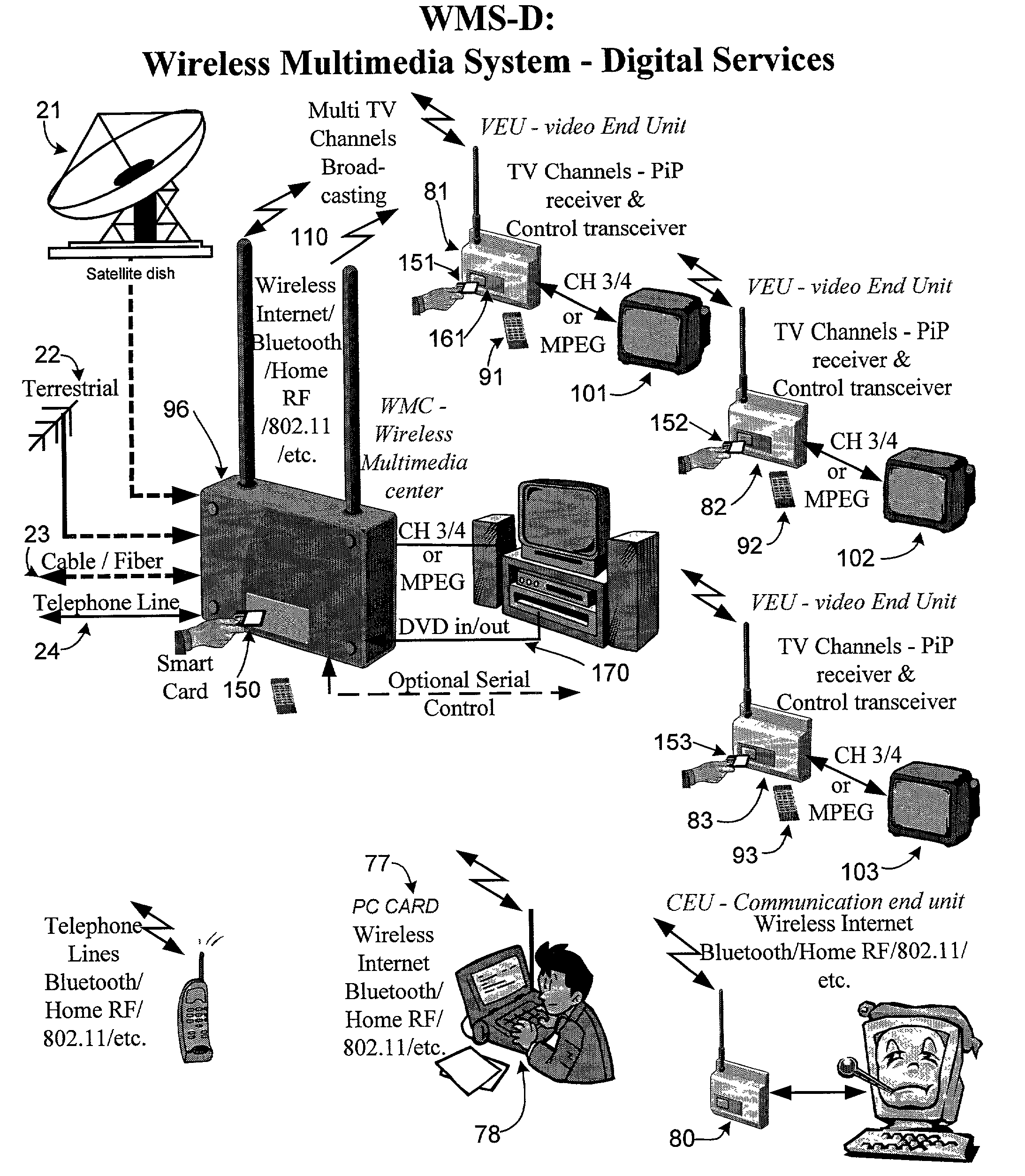
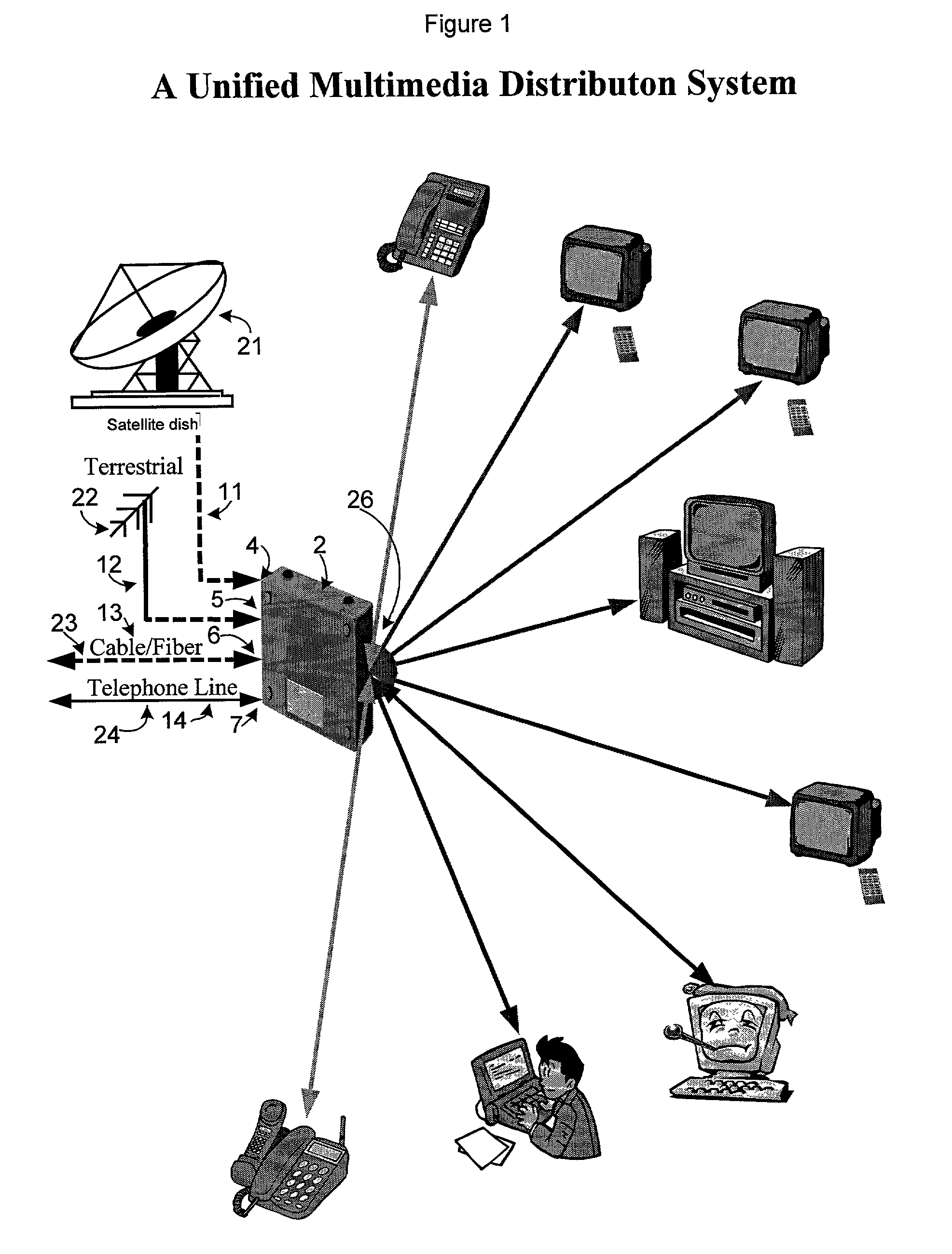
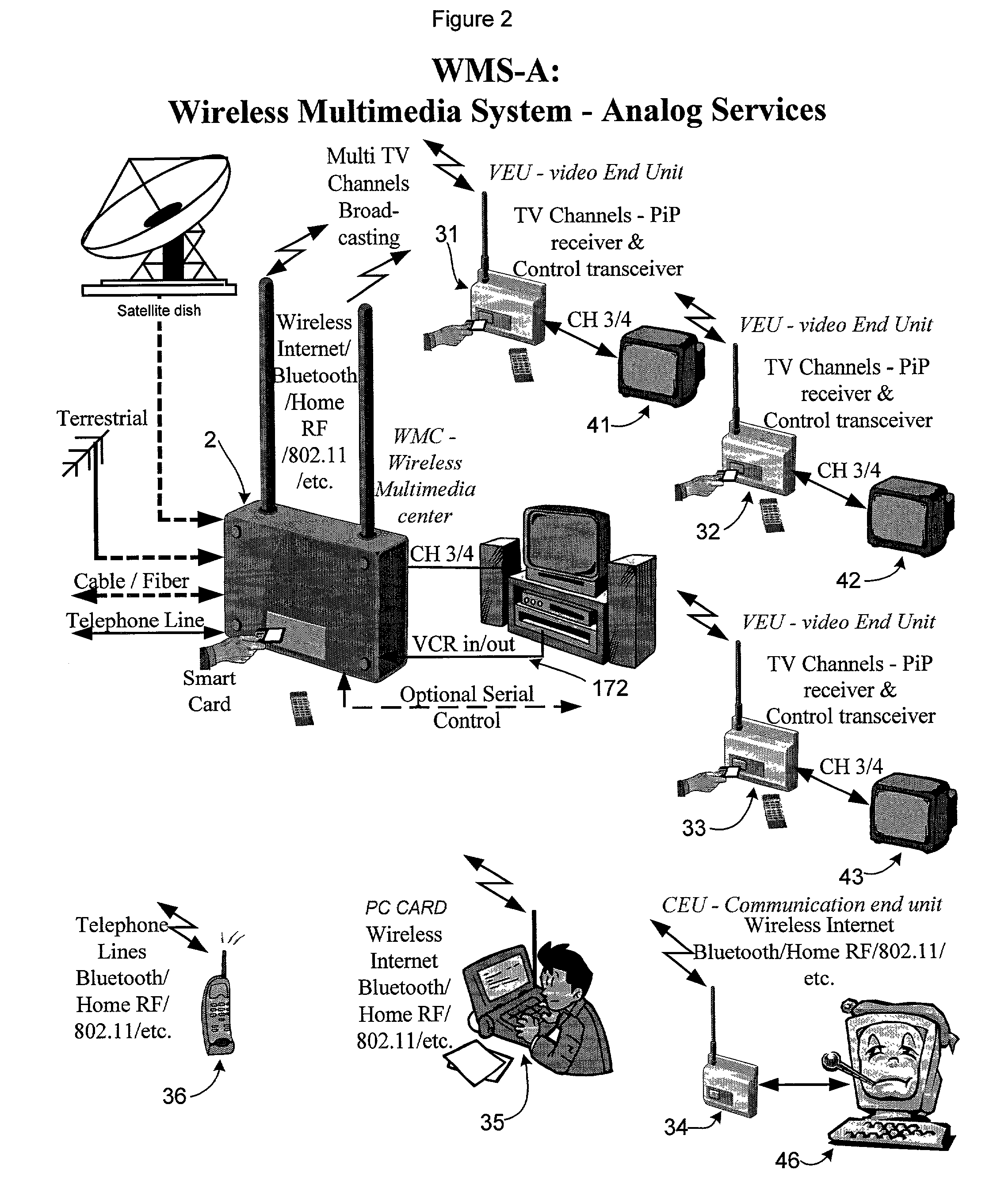
[0019]As in FIG. 1, this invention relates to a wireless distribution system for home or business, comprising a unitary distribution box 2, called a wireless multimedia center (WMC), which has inputs for receiving signals 11-14 from one or more of:[0020]a satellite dish 21;[0021]a terrestrial antenna 22;[0022]a cable input / output line 23; and / or[0023]a telephone or data line 24 [ISDN, DSL, etc].

[0024]Signals input are then re-broadcast, using OFDM technology, throughout the premises by low energy digital transmissions 26, at energy levels just above background radiation. As in FIG. 2, these signals are transmitted to, and received by, individual transceivers 31-36 located throughout the premises. These transceivers are presently contemplated as:[0025]video end unit 31-33, for[0026]television receivers 41-43;[0027]VCRs;[0028]AM / FM broadcasting;[0029]Communications end unit 34-36, for:[0030]computers 46;[0031]telephones 36,[0032]faxes,[0033]answering machines,[0034]other telephonic de...


PUM


Abstract

A customer premises installation has a wireless multimedia center (WMC) for reception from one or more signal sources and for distribution of segments of signals from signal sources through the wireless multimedia center to a plurality of end units, in which the signals include video signals and broadband data. The wireless multimedia center receives all the signals and distributes segments of said signals via a transmitter. The video signals are transmitted by orthogonal frequency division multiplexing in which all signals are added together and summed as an orthogonal array having dimensions of time, frequency and amplitude, to transmit spread spectrum multiplexed signals. Each pulse has sufficiently long individual pulse widths to defeat multi-path, reflection and absorption phase induced losses. The video signals are distributed to one or more end units. The end units communicate with the wireless multimedia center, controlling which segments of which signals are distributed to each end unit.

Description

CROSS-REFERENCE TO RELATED APPLICATIONS[0001]This converts Provisional Patent Application 60 / 185,862 to a utility application taking benefit under 119(e) of its filing date of Feb. 29, 2000.STATEMENT REGARDING FEDERALLY SPONSORED RESEARCH OR DEVELOPMENT[0002]None.REFERENCE TO A MICROFICHE APPENDIXSee 37 CFR 1.96(C)[0003]None.BACKGROUND OF THE INVENTION[0004](1) Field of the Invention[0005]This invention relates to a wireless distribution system for home or business comprising a unitary distribution box, called a wireless multimedia center, which has inputs for receiving signals from one or more sources. Signals are then re-broadcast throughout the site by low energy digital transmissions, at energy levels just above background radiation. These signals are transmitted to and received by individual transceivers, called end units (EU), located throughout the site.[0006](2) Description of Related Art Including Information Disclosed Under 37 CFR 1.97 and 37 CFR 1.98[0007]An information d...

Claims


Application Information

Patent Timeline
Patent Type & Authority Patents(United States)
IPC IPC(8): H04N7/173H04N7/20H04N7/14H04N7/16H04B1/707H04B7/185H04L12/28H04L12/56
CPCH04B7/1858H04B2201/709709H04Q2213/13098H04Q2213/13242H04Q2213/13248H04Q2213/13376H04Q2213/13389H04W28/04H04W88/04
Inventor EIGER, TUVIABERCHIN, URIEL
Owner BE LABS
Learn More