
Safety and arming device for high-G munitions

a safety and arming device technology, applied in the field of microelectromechanical systems, can solve the problems of large size, relatively expensive manufacturing and assembly, and not specifically designed for withstanding very hard launches

Inactive Publication Date: 2010-10-26
ALCATEL-LUCENT USA INC
View PDF17 Cites 2 Cited by
  • Summary
  • Abstract
  • Description
  • Claims
  • Application Information

AI Technical Summary

Benefits of technology

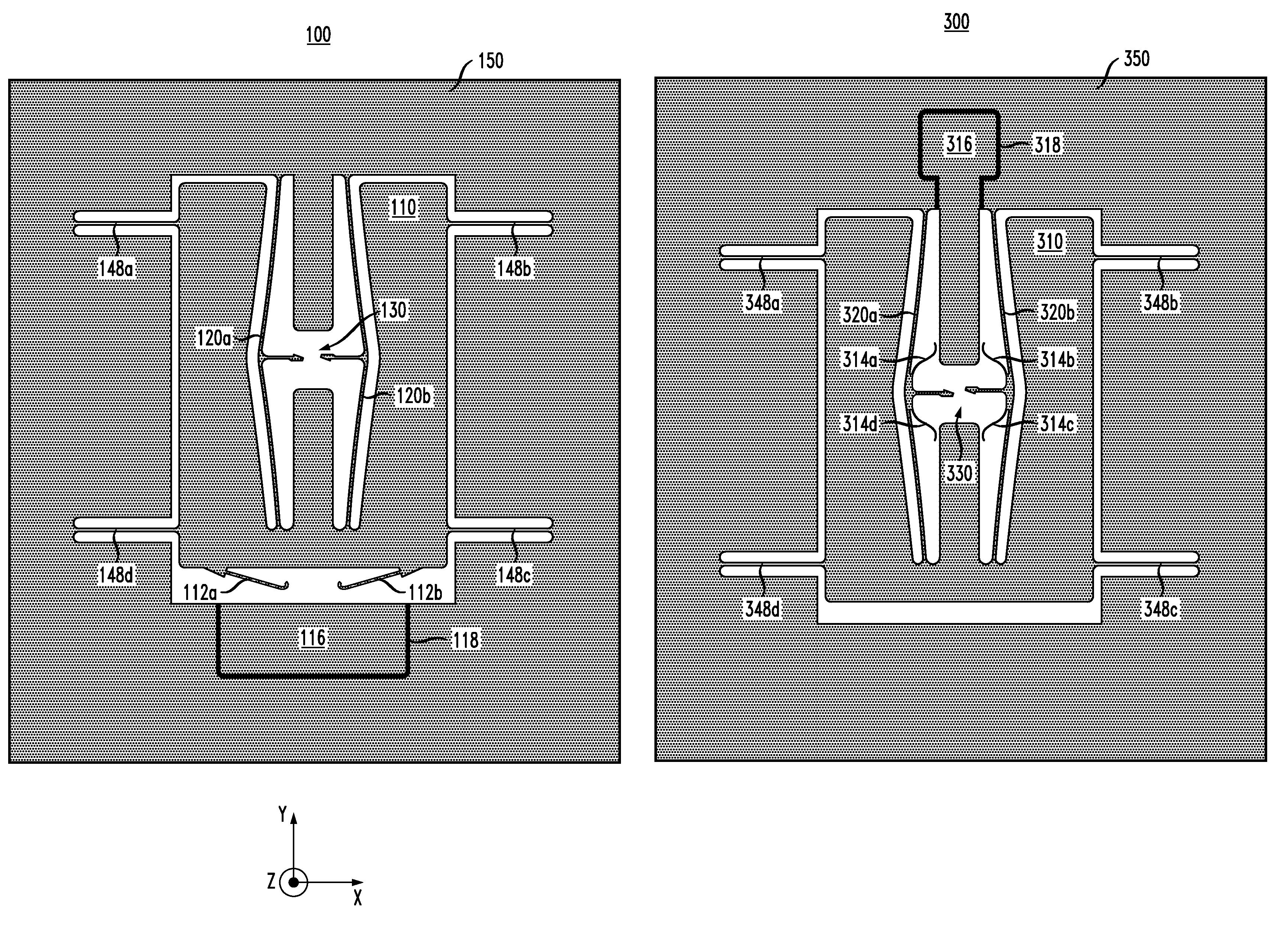
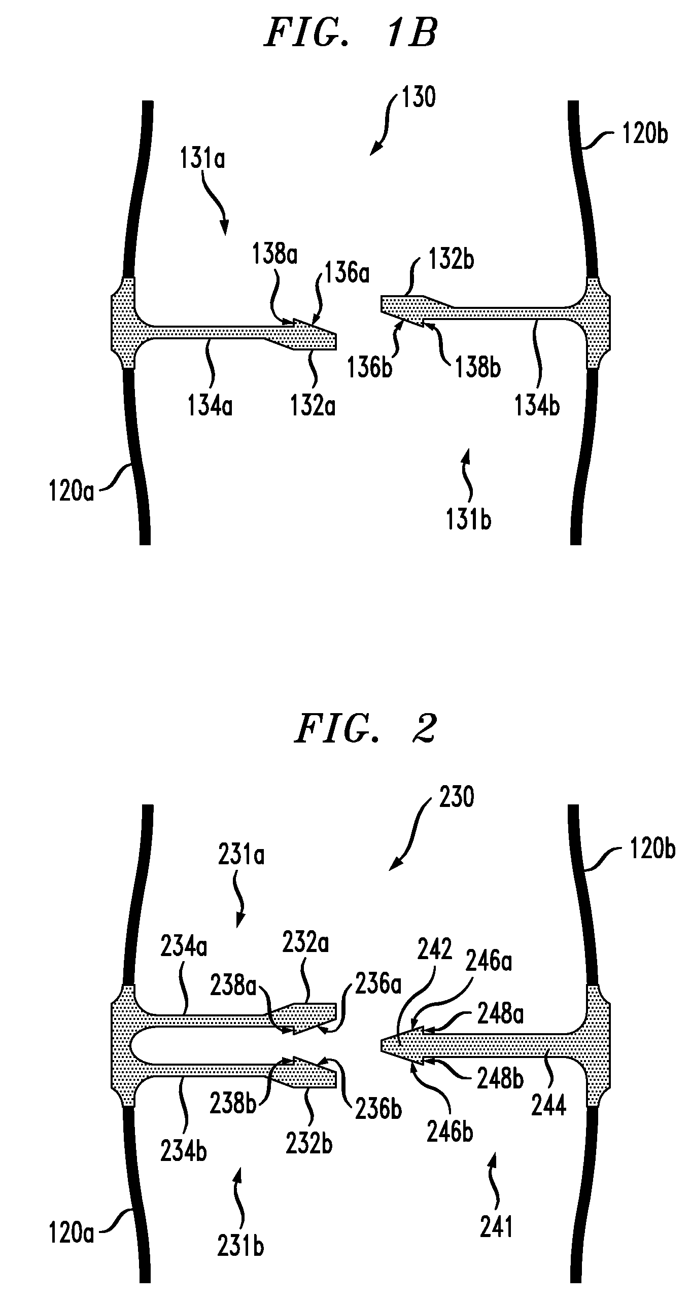
[0008]A bowed spring of the S&A device is a nonlinear spring that can perform a function analogous to that of a mechanical stop. However, unlike a mechanical stop, the bowed spring is able to stop the shuttle gradually and without imparting on the shuttle a “hard” physical contact with an external structure. As a result, occurrence of damaging shock waves, e.g., caused by such hard physical contacts, is advantageously reduced, which enables S&A devices of the invention to function properly at accelerations as high as about 80,000 g.

Problems solved by technology

One problem with that device is that it is relatively large (e.g., several centimeters) in size and relatively expensive to manufacture and assemble.
While the latter devices are advantageously relatively small (e.g., about 1 mm) in size and relatively inexpensive to manufacture, they are not specifically designed for withstanding very hard launches, e.g., those causing initial accelerations of over 50,000 g.

Method used


Image

  • Safety and arming device for high-G munitions
  • Safety and arming device for high-G munitions
  • Safety and arming device for high-G munitions

Examples


Embodiment Construction

[0016]One representative MEMS-based safety and arming (S&A) device has a shuttle movably connected to a frame by one or more linear springs. As used herein, the term “linear spring” means that the spring force is substantially proportional to the spring deformation (e.g., expressed in terms of displacement relative to an undeformed state) over at least a significant portion of the operating range of the spring. The S&A device becomes armed, e.g., when the shuttle displacement causes an electrical switch controlling the fire train to close. The springs provide a potential-energy barrier against accidental arming due to mishandling of the artillery shell, such as an accidental drop from a truck bed. However, if the S&A device is subjected to acceleration that exceeds the arming threshold, then the resulting inertial force causes the shuttle to overcome the potential-energy barrier and close the switch.

[0017]The S&A device typically employs a latching mechanism designed to keep the swi...


PUM


Abstract

A representative embodiment of the invention provides a MEMS-based safety and arming (S&A) device having a shuttle movably connected to a frame by one or more bowed springs. The device has an electrical path adapted to electrically connect the frame and a contact pad. In the initial state, the electrical path has an electrical break. If the inertial force acting upon the shuttle (e.g., during launch) reaches or exceeds a first threshold value, then displacement of the shuttle with respect to the frame causes the electrical break to close. If the inertial force reaches or exceeds a second threshold value greater than the first threshold value, then a latching mechanism employed in the S&A device latches to keep the electrical break irreversibly closed thereafter.

Description

GOVERNMENT CONTRACT[0001]This invention was made with Government support under Contract No. DAAE30-03-D-1013-10 awarded by the Picatinny Arsenal. The Government has certain rights in this invention.BACKGROUND OF THE INVENTION[0002]1. Field of the Invention[0003]The present invention relates to micro-electromechanical systems (MEMS) and, more specifically, to MEMS-based safety and arming devices.[0004]2. Description of the Related Art[0005]An artillery shell is typically equipped with a safety and arming (S&A) device that permits detonation of the explosive charge only after the projectile has experienced a valid progression of physical launch conditions, including the large initial acceleration in the gun barrel. The S&A device functions with sequential interlocks to remove a barrier in the fire train and / or to move out-of-line fire-train components into alignment. Once armed, the device permits initiation of the explosive, e.g., with an electrical discharge or a laser pulse, which ...

Claims


Application Information

Patent Timeline
Patent Type & Authority Patents(United States)
IPC IPC(8): F42C15/24
CPCF42C15/00F42C15/24F42C15/40
Inventor GREYWALL, DENNIS S.
Owner ALCATEL-LUCENT USA INC
Learn More