
MICR reader

a reading mechanism and micr technology, applied in the field of micr reading mechanism, can solve the problems of failure of reading, impossible reading, and inability to read, and achieve the effect of preventing the applicability of pressur

Inactive Publication Date: 2010-10-12
PFU LTD
View PDF12 Cites 1 Cited by
  • Summary
  • Abstract
  • Description
  • Claims
  • Application Information

AI Technical Summary

Benefits of technology

The invention provides a MICR reading mechanism for accurately reading MICR characters in a scanner with a center paper feeding mechanism, even when documents of different paper sizes are loaded in a mixed form. The mechanism includes a MICR reading head and a sensor to detect the end portion of the medium in a perpendicular direction. The MICR reading head is movable to a predetermined position at a predetermined distance from the end portion detected by the sensor. The mechanism may also include a pressure application roller or a pressure applier to bring the medium into close contact with the MICR reading head, and a contact prevention member to prevent the pressure applier from coming into contact with the MICR reading head when it is moved. The predetermined position may correspond to the position where the MICR character is printed on the medium. The mechanism may also include a correction member to correct any skew of the medium.

Problems solved by technology

Therefore, since the MICR characters do not pass over the MICR reading head, reading has been impossible.
In addition, with a related scanner having the center paper feeding mechanism, there are cases where the paper skews, as shown in FIG. 4B, so that there have been cases where reading fails.
Therefore, it is impossible to allow the MICR characters to accurately pass over the MICR reading head, making reading impossible.
In particular, in cases where documents of different paper sizes are loaded in a mixed form, the end portions in the width direction of the paper serving as the reference for the printing position of the MICR characters become misaligned for each sheet of paper, so that reading has been impossible.

Method used


Image

  • MICR reader
  • MICR reader
  • MICR reader

Examples


embodiment

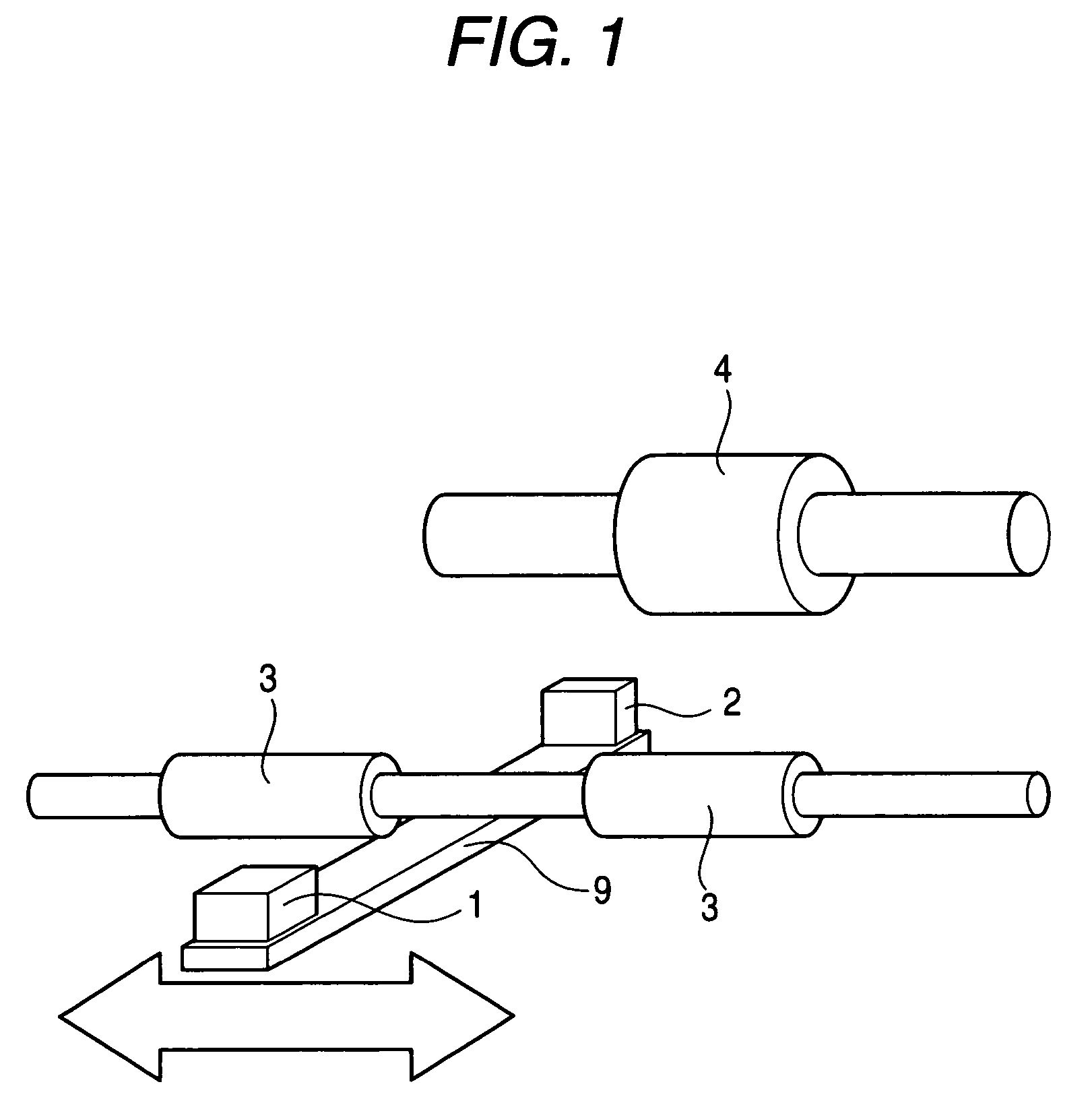
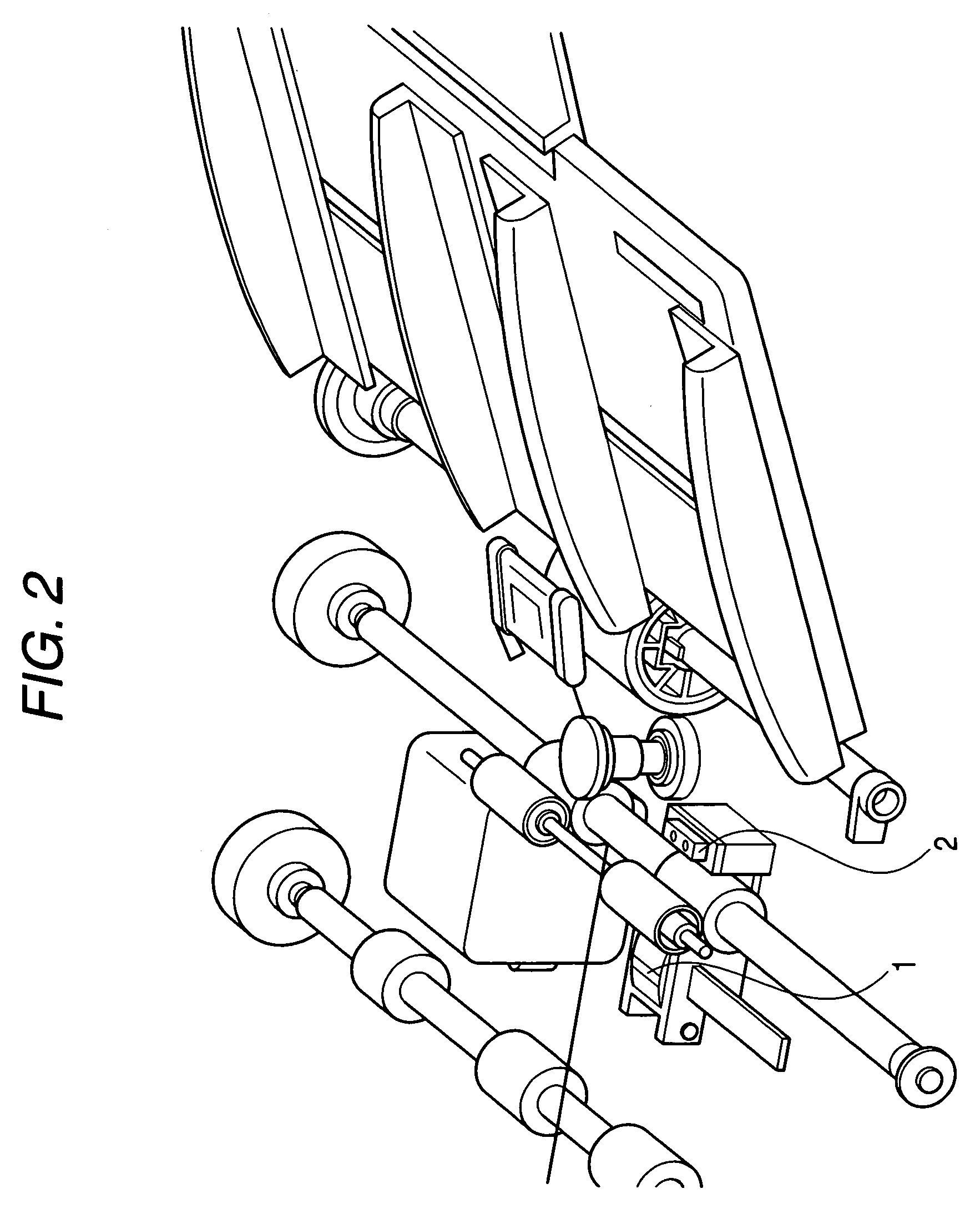
[0043]Referring to the drawings, a description will be given of an embodiment in accordance with the invention. It should be noted that in the description below, the same portions are denoted by the same reference numerals, and a detailed description thereof will be omitted in some cases.

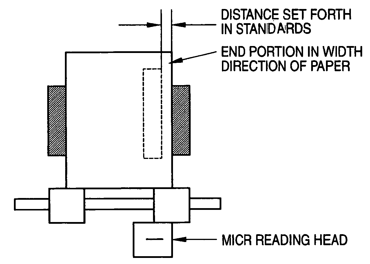
[0044]As shown in FIGS. 1 and 2, the paper fed by a feed roller 4 and transported by transport rollers 3 has its end portion in the width direction detected by a sensor 2 for detecting an end portion in the width direction of the paper.

[0045]As a result, a MICR reading head 1 connected to the sensor 2 by a connecting member 9, for detecting an end portion in the width direction of the paper is moved from the detected end portion in the width direction of the paper so that the MICR characters printed at a predetermined position set forth by the standards pass over the MICR reading head 1. At this time, the MICR reading head 1 is displaced from the sensor 2 at a predetermined distance that is a distan...


PUM


Abstract

A MICR reading head is operable to read a MICR character printed on a medium fed in a first direction. A sensor is operable to detect an end portion in a second direction perpendicular to the first direction of the medium. The MICR reading head is movable to a predetermined position at a predetermined distance from the end portion detected by the sensor.

Description

BACKGROUND OF THE INVENTION[0001]The present invention relates to a MICR reading mechanism for reading MICR characters printed with a special magnetic ink, and concerns the realization of the accurate reading of MICR characters by a scanner having a center paper feeding mechanism.[0002]MICR (magnetic ink character recognition) characters are such that the position on the paper (medium) where the characters are to be printed has been determined by standards, and that which constitutes its reference is the distance from an end portion of the printed paper in a direction (width direction) perpendicular to a feeding direction in which the paper fed. In addition, the sizes of the characters have also been determined by the standards. When the MICR characters are read, it must be ensured that the characters pass over the reading head in conformity with the position and the size prescribed in these standards.[0003]In the case of a scanner having a center paper feeding mechanism, it is nece...

Claims


Application Information

Patent Timeline
Patent Type & Authority Patents(United States)
IPC IPC(8): G06K7/08
CPCG06K9/186G06K9/3275G06V30/2253G06V10/243
Inventor KAWAI, MASAYOSHIKITAGAWA, YASUHIKO
Owner PFU LTD
Learn More