
Ink supply apparatus and ink jet recording apparatus

a technology of ink jet and recording head, which is applied in printing and other directions, can solve the problems of ink supply failure, recording head, and ink leakage not from the main, and achieve the effect of preventing unnecessary ink leakag

Active Publication Date: 2010-10-05
CANON KK
View PDF4 Cites 3 Cited by
  • Summary
  • Abstract
  • Description
  • Claims
  • Application Information

AI Technical Summary

Benefits of technology

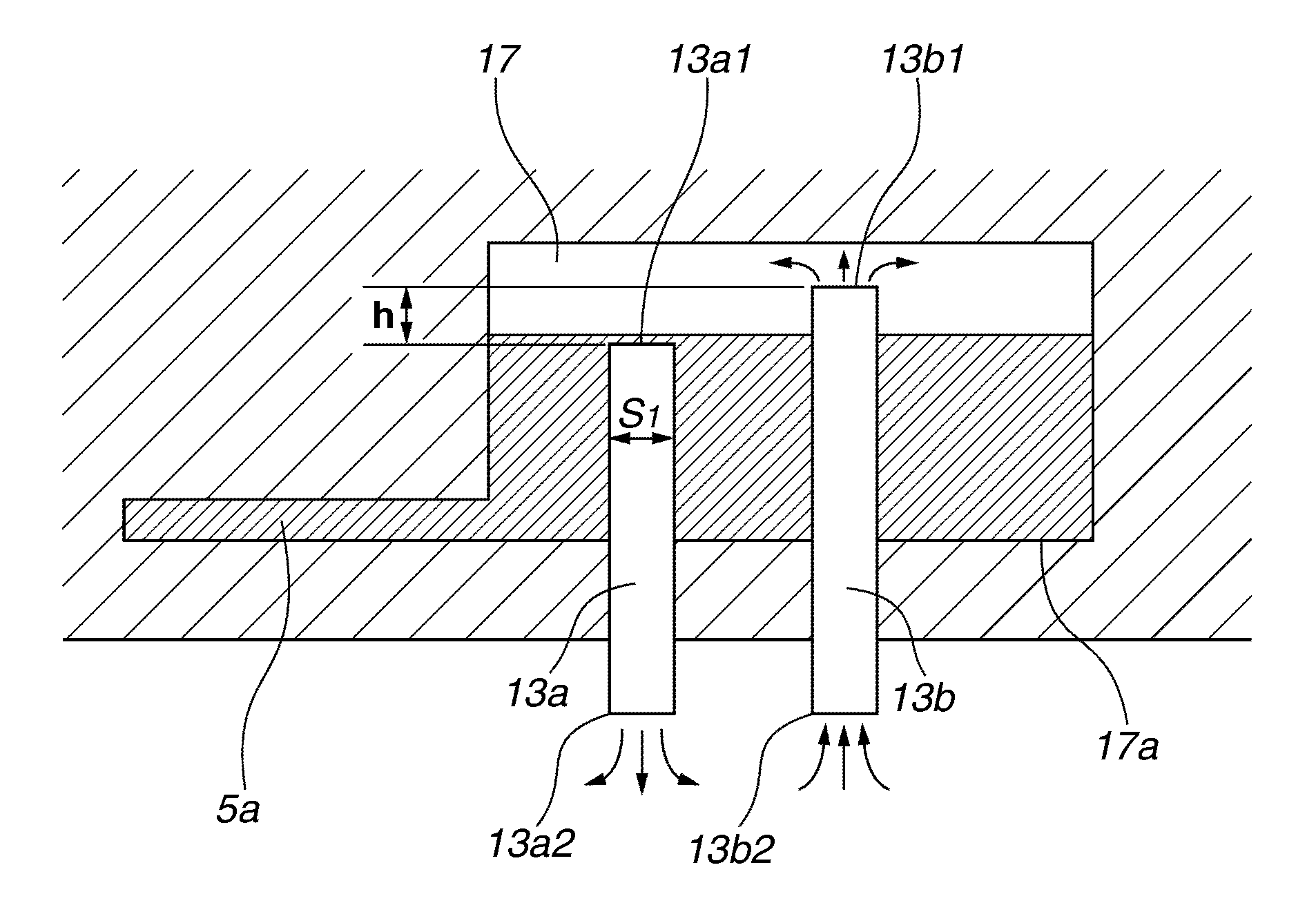
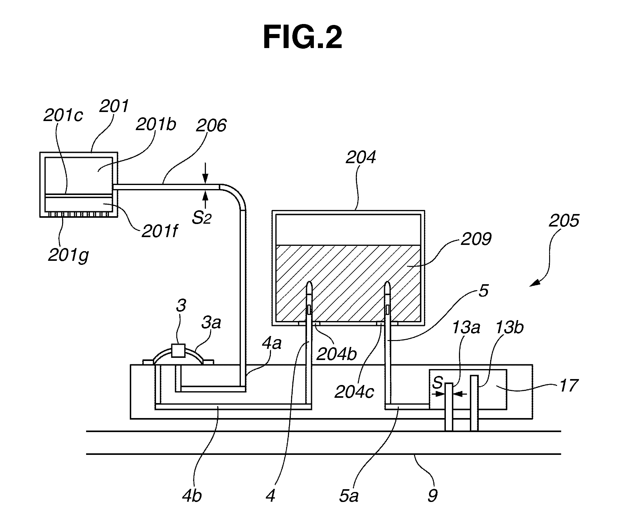
The present invention is about an ink supply apparatus and ink jet recording apparatus that can prevent ink from leaking out of the ink tank. The invention includes an atmosphere communication chamber that connects to the ink tank, two hollow tubes that connect the chamber to the outside air, and a first air path and a second air path that have different heights in a direction of gravity. The invention also reduces change in negative pressure inside the tank and maintains a constant air and liquid exchangeable state between the hollow tubes and the outside air, which prevents ink leakage.

Problems solved by technology

The air permeating and intruding through a resinous material of the tube 106, or the air dissolved and contained inside the ink can cause air accumulation inside the sub tank 101b, which causes a problem.
Moreover, the ink supply can fail when the ink inside the sub tank 101b becomes empty.
However, the conventional example described above has a problem that the ink may leak not from the main tank 104 side but from the recording head 101 side.
Moreover, once the apparatus is inclined, meniscus of the recording head is broken.

Method used


Image

  • Ink supply apparatus and ink jet recording apparatus
  • Ink supply apparatus and ink jet recording apparatus
  • Ink supply apparatus and ink jet recording apparatus

Examples


first exemplary embodiment

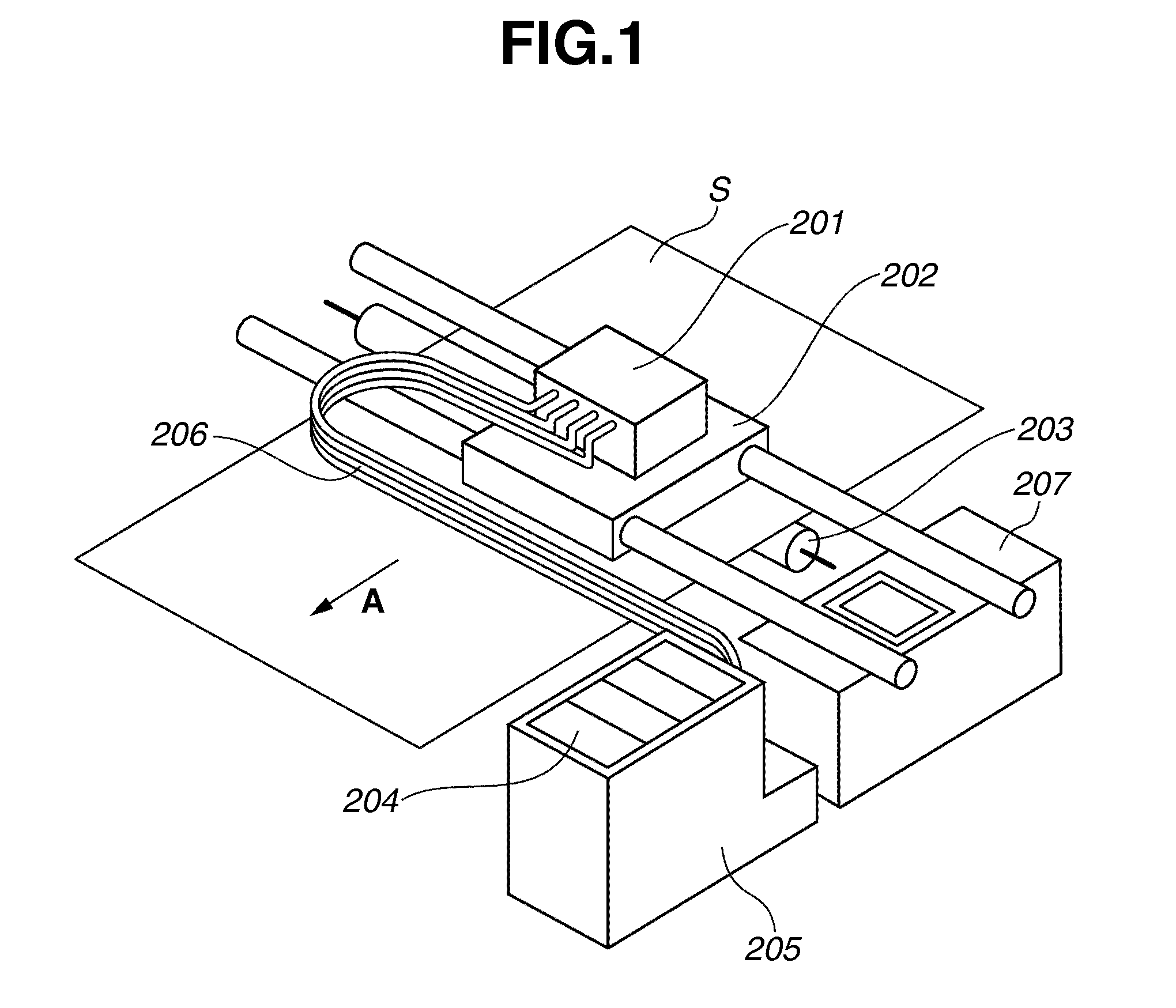
[0027]FIG. 1 illustrates a perspective view showing the configuration of the ink jet recording apparatus in accordance with exemplary embodiments of the present invention.

[0028]The ink jet recording apparatus of FIG. 1 is capable of repeating the reciprocal motion of a recording head 201 (main scanning), and the conveyance of a recording sheet S (recording medium) by a predetermined pitch (subscanning) so that the recording head 201 can selectively discharge ink in synchronization with these motions. The ink sticks to the recording sheet S to form a character, a symbol, or an image. Examples of the recording sheets include an ordinary recording paper, a special paper, and an OHP film.

[0029]Referring to FIG. 1, the recording head 201 is detachably mounted on a carriage 202. The carriage 202 is slidably supported by two guide rails and is reciprocated along the guide rails by a drive unit such as a motor (not illustrated). The recording sheet S is conveyed by a conveying roller 203 in...


PUM


Abstract

An ink supply apparatus for supplying ink from an ink tank to a recording head includes an atmosphere communication chamber that is connected to the ink tank, a first hollow tube that connects the atmosphere communication chamber to the outside air wherein one end is extended into the atmosphere communication chamber, and a second hollow tube that connects the atmosphere communication chamber to the outside air wherein one end is extended into the atmosphere communication chamber. The length of extension of the second hollow tube is different from the length of extension of the first hollow tube.

Description

BACKGROUND OF THE INVENTION[0001]1. Field of the Invention[0002]The present invention relates to an ink supply apparatus and an ink jet recording apparatus.[0003]2. Description of the Related Art[0004]Japanese Patent Application Laid-Open No. 2002-307709 (corresponding to U.S. Pat. No. 6,805,437) discusses an ink supply system of an ink jet recording apparatus, which is an example of the conventional ink jet recording apparatus shown in FIG. 4.[0005]A recording head 101 has a sub tank 101b. The sub tank 101b holds a predetermined amount of ink supplied through a tube 106 from a main tank 104 mounted on the main body of the ink jet recording apparatus.[0006]The main tank 104 is detachably mounted on a supply unit 105, which is provided with an ink supply port sealed by a rubber stopper 104b and an atmosphere introduction port sealed by a rubber stopper 104c, at its base portion. The main tank 104 is an air-tight container as a unit. The ink 109 is directly contained inside the main t...

Claims


Application Information

Patent Timeline
Patent Type & Authority Patents(United States)
IPC IPC(8): B41J2/175B41J2/19
CPCB41J2/175B41J2/17509
Inventor WATANABE, SHIGERU
Owner CANON KK
Learn More