
Turbocharger configuration for an outboard motor

a technology of outboard motors and turbochargers, which is applied in the direction of marine propulsion, steam power plants, vessel construction, etc., can solve the problems of limited space available for components such as turbochargers, damage to the operability of the turbocharger, and leakage of significant amounts of fuel

Inactive Publication Date: 2010-10-05
BRUNSWICK CORPORATION
View PDF18 Cites 32 Cited by
  • Summary
  • Abstract
  • Description
  • Claims
  • Application Information

AI Technical Summary

Problems solved by technology

The central aperture of a used turbine housing often is corroded such that the central aperture is enlarged and allows significant leakage.
When turbochargers are used in marine applications, particularly in outboard motor applications, several additional problems must be addressed that do not normally occur in automotive or other non-marine applications.
One problem relates to the limited space available for components, such as turbochargers, under the cowl of the outboard motor.
Another problem relates to the potential inversion of water, from a body of water on which the marine vessel is operated, during certain conditions when internal pressures within the exhaust system and cylinders can induce the upward flow of water in a reverse direction through the exhaust system and toward the cylinders.
In addition to the potential damage that this type of water inversion can cause to the engine, it can also draw water into and through the turbocharger and result in serious damage to the operability of the turbocharger.

Method used


Image

  • Turbocharger configuration for an outboard motor
  • Turbocharger configuration for an outboard motor
  • Turbocharger configuration for an outboard motor

Examples


Embodiment Construction

[0030]Throughout the description of the preferred embodiment of the present invention, like components will be identified by like reference numerals.

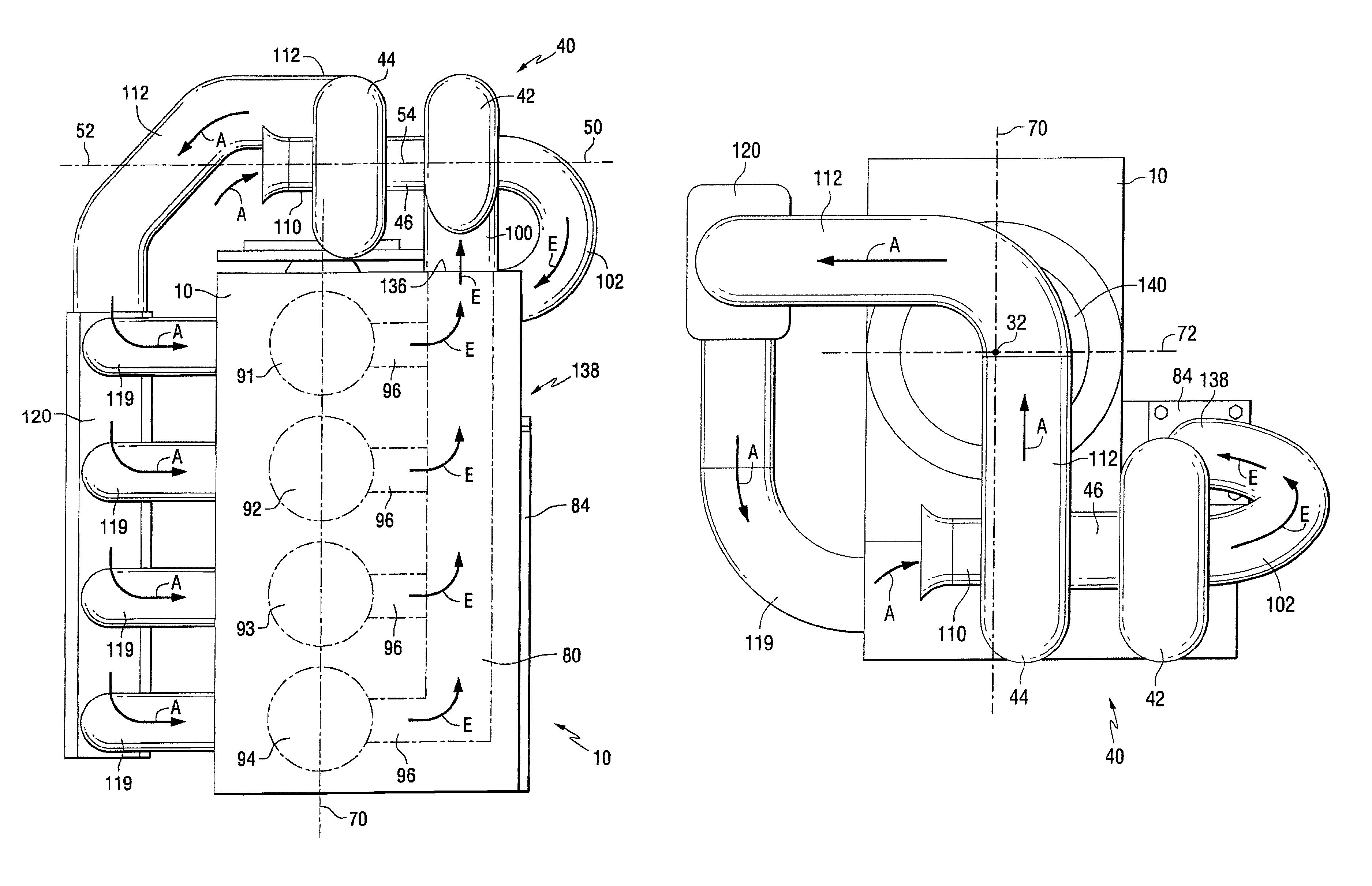
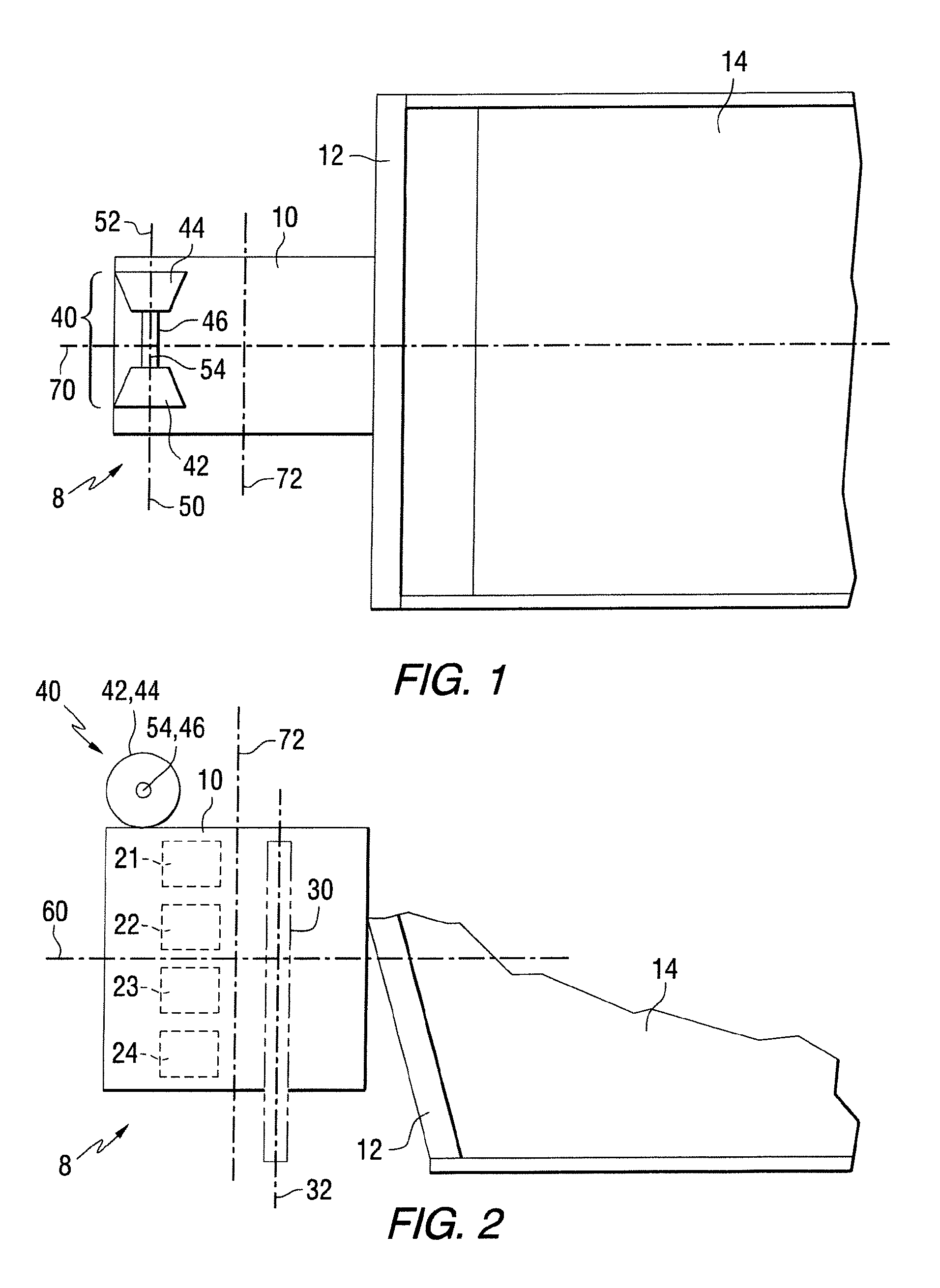
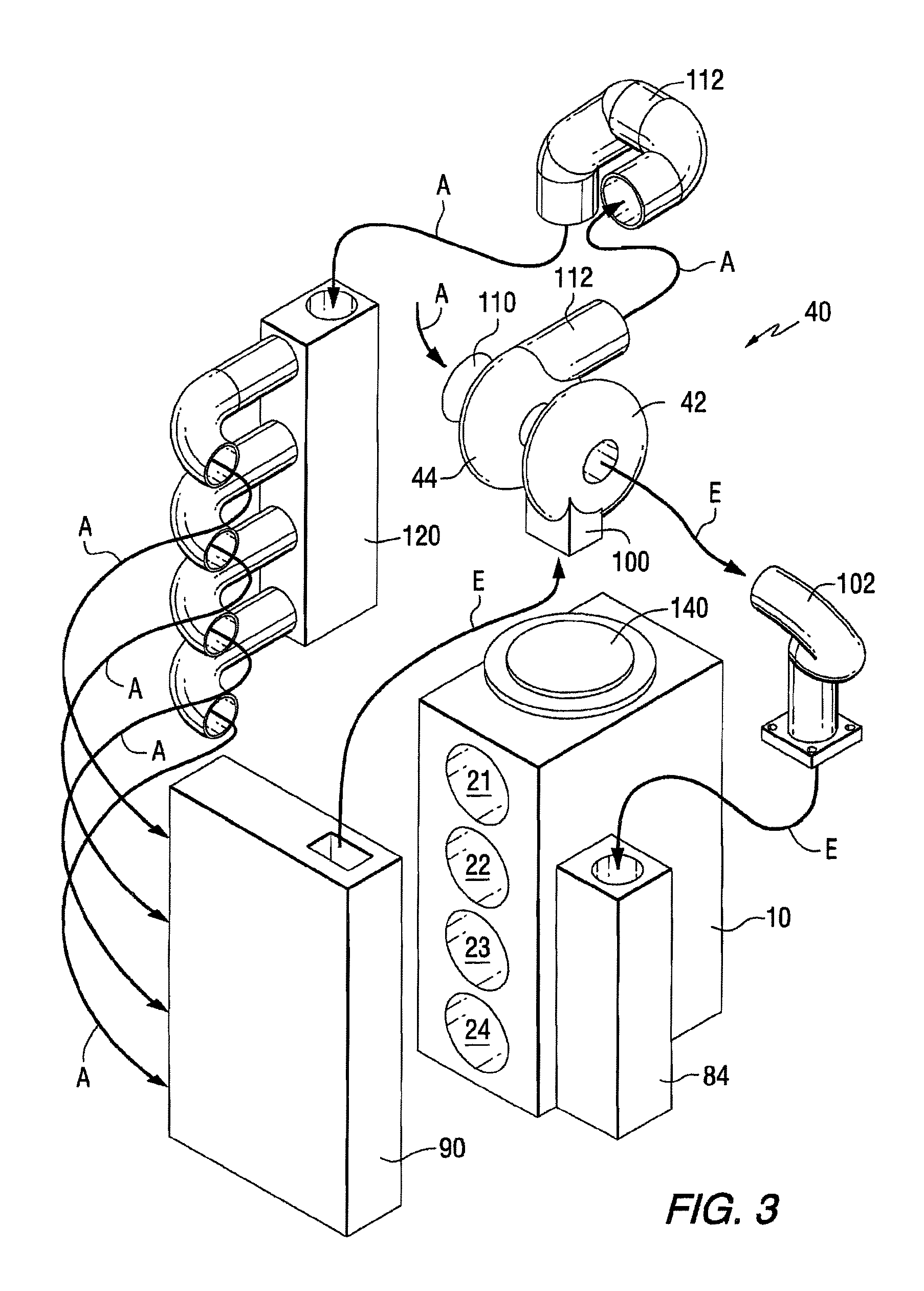
[0031]FIGS. 1 and 2 are highly simplified schematic representations of outboard motors. The purpose of FIGS. 1 and 2 is to describe certain terminology that will be used below in the description of the preferred embodiment of the present invention. These figures are not intended to be complete or show a fully illustrated outboard motor. Throughout the Figures, arrows A and E designate the air flow and exhaust flows, respectively.

[0032]In FIG. 1, an engine 10 of an outboard motor 8 is shown attached to a transom 12 of a marine vessel 14. FIG. 1 is a top view of the outboard motor 8 and marine vessel 14 and FIG. 2 is a side view.

[0033]In FIG. 2, the engine 10 is shown with four cylinders, 21-24, represented by dashed lines. In addition, a portion of a crankshaft 30 is shown. The crankshaft 30 is supported for rotation about a generally ve...


PUM


Abstract

A marine propulsion device is provided with a turbocharger that is located above all, or at least a majority of, the cylinders of an engine. The exhaust gases are directed to one side of the engine and the compressed air is directed to an opposite side of the engine. The turbocharger is located at a rear portion of the engine behind the crankshaft.

Description

BACKGROUND OF THE INVENTION[0001]1. Field of the Invention[0002]The present invention relates generally to an outboard motor with a turbocharger and, more particularly, to a marine propulsion system in which a turbocharger is disposed above most of, if not all, of the cylinders of an engine in which the cylinders are vertically distributed and, in certain embodiments of the present invention, the turbocharger is located at a rearward portion of the engine above all of the cylinders.[0003]2. Description of the Related Art[0004]Turbochargers are well known by those skilled in the art for use in conjunction with internal combustion engines. Exhaust gases are used to drive a turbine which is connected in torque transmitting relation with a compressor. The compressor provides pressurized charge air that is used, within the cylinders, in the combustion process. Turbochargers are also known to those skilled in the art for use in conjunction with marine propulsion systems, including outboar...

Claims


Application Information

Patent Timeline
IPC IPC(8): F02B33/00B63H21/10B63H21/38F02B37/00
CPCF02B67/10B63B2770/00F01N2590/021F02B37/02
Inventor BROMAN, JEFFREY J.MUELLER, ERIC S.
Owner BRUNSWICK CORPORATION
Learn More