
Process for forming multilayer containers

a multi-layer container and container technology, applied in the field of plastic articles, can solve the problems of pp and pet containers being inherently subject to gas transmission, permeability problems becoming more acute, and gas permeability clearly being detrimental

Active Publication Date: 2010-09-28
BECTON DICKINSON & CO
View PDF14 Cites 43 Cited by
  • Summary
  • Abstract
  • Description
  • Claims
  • Application Information

AI Technical Summary

Benefits of technology

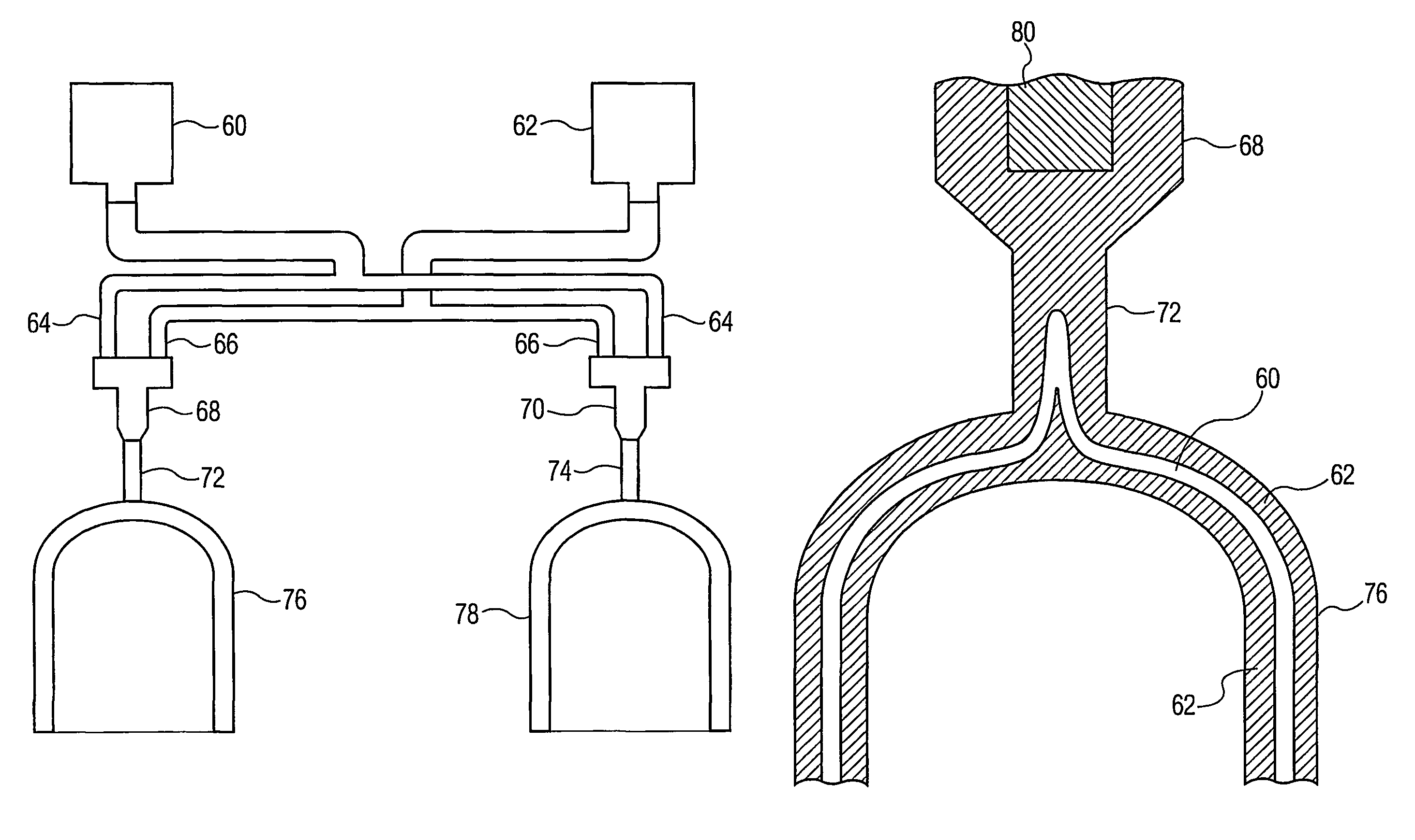
The invention provides a process for making improved containers, such as blood collection tubes and syringe barrels, by using a first and second molten polymeric material that are non-compatible. The process involves directing the materials into a mold cavity and co-flowing them to form the bottom wall of the container. The resulting container has a unique structure with inner and outer polymeric skin layers and a core layer, which eliminates the need for adhesive or tie layers between the distinct polymers. The technical effect of this process is the creation of containers with improved strength and flexibility that meet the needs of various applications.

Problems solved by technology

As a result, PP and PET containers are inherently subject to transmission of gases.
As the medical industry begins to place increased emphasis on the use of plastic medical products, these permeability problems have become more acute.
Such performance standards generally include the ability to maintain greater than about 90% original draw volume over a one year period, and gas permeability clearly is detrimental to this need.

Method used


Image

  • Process for forming multilayer containers
  • Process for forming multilayer containers
  • Process for forming multilayer containers

Examples


example 1

[0057]A PET tube and two multilayer tubes were made by a coinjection process as described above. All tubes were 16×100 mm size.

[0058]Run 1: PET tube with skin layer and core layer both PET.

[0059]Run 2: PET-COC-PET tube with inner and outer skin layers of PET and core layer COC.

[0060]Run 3: PEN-COC-PEN tube with inner and outer skin layers of PEN and core layer of COC.

[0061]Twenty tubes from each run were filled with 1 ml of water, evacuated to 200 mm Hg, and stoppered. The tubes were weighed. Ten tubes from each run were placed into a storage chamber at 25° C. and 50% relative humidity, and ten tubes from each run were placed in a storage chamber at 40° C. and 50% relative humidity. Average weight loss (i.e., water loss) for each run after 56 days is shown in Table 1.

[0062]

TABLE 1Average water loss (mg)Average water loss (mg)Tube@ 25° C. after 56 days@ 40° C. after 56 days158.3163.9213.2 50.536.0not measured

example 2

[0063]Three layer tubes of PP skin material and EVOH core material were fabricated according to the process described above. The tubes were 13 mm×75 mm, 2.0 ml draw tubes. Thirteen runs were made, the runs having variation in (1) the amount (volume percent) of EVOH present, and (2) the nominal extent of coverage of the EVOH in the tube, as shown in Table 2 below.

[0064]

TABLE 2NominalEVOH locatedEVOH locatedEVOH locatedSubstantiallyEVOHNo0.500 inches0.200 inches0.500 inchesCompleteCoverage inEVOH infrom top edgefrom top edgefrom bottom ofCoverage ofTube tubeand belowand belowtube and aboveEVOHNominalRun #1————0 vol. % EVOHNominal—Run #5 Run #4 Run #3 Run #2 5 vol. % EVOHNominal—Run #9 Run #8 Run #7 Run #6 8 vol. % EVOHNominal—Run #13Run #12Run #11Run #1010 vol. %EVOH

[0065]For each run, multiple wet and dry tubes were prepared, and tested. Wet tubes were prepared by first weighing the empty tube, placing 0.2 ml of water therein, and reweighing. The wet tubes were then conventionally ev...


PUM

PropertyMeasurementUnit
thicknessaaaaaaaaaa
RHaaaaaaaaaa
internal diameteraaaaaaaaaa

Abstract

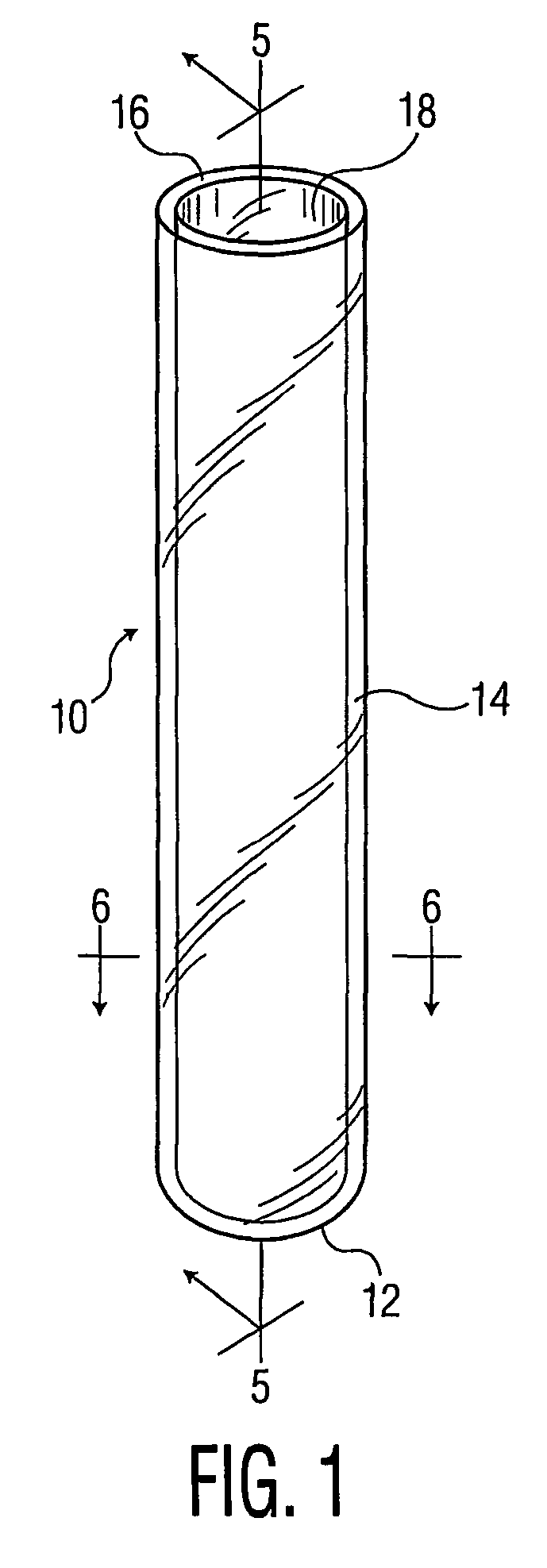
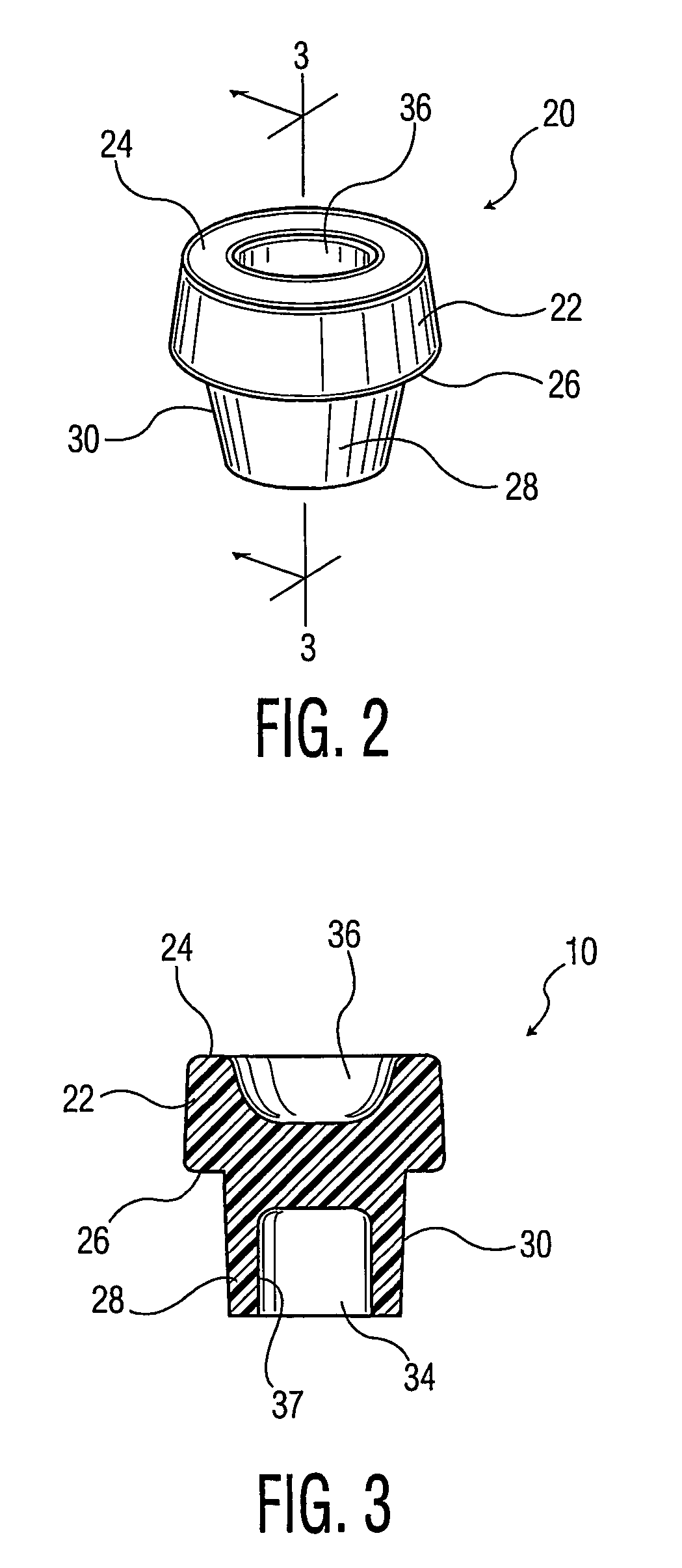
A co-injection process is provided for fabricating improved multi-layer containers, including but not limited to blood collection tubes, evacuated blood collection tubes, culture bottles, centrifuges tubes, and syringe barrels. The container includes a tube (10) having a bottom wall (12) and a side wall (14) with an open end (18). The container can be provided with a stopper having an upper portion (22) and a skirt with an outside portion (30), a well (34) and a cavity (36). The tube and stopper assembly can be used for medical purposes including containing a blood sample within an enclosed interior space (40).

Description

BACKGROUND OF THE INVENTION[0001]1. Field of the Invention[0002]This invention relates to plastic articles and more particularly relates to medical articles having improved gas and liquid vapor barriers.[0003]2. Description of the Related Art[0004]Polypropylene (PP) has long been used in molding and extruding operations for articles such as plastic medical containers and films for the food packaging industry. Polyethylene terephthalate (PET) has more recently been used in molding and extruding operations for these articles. However, PP and PET are somewhat permeable to nitrogen, oxygen, and other gases and vapors. As a result, PP and PET containers are inherently subject to transmission of gases. As the medical industry begins to place increased emphasis on the use of plastic medical products, these permeability problems have become more acute.[0005]In particular, evacuated blood collection tubes must meet certain performance standards. Such performance standards generally include t...

Claims


Application Information

Patent Timeline
Patent Type & Authority Patents(United States)
IPC IPC(8): B29C45/16B29C45/13B29C45/72B65D1/00A61B5/15B01L3/14B29K23/00B29K45/00B29K67/00B29L24/00B32B1/00
CPCA61B5/1438B01L3/5082B29C45/1642A61B5/14B01L2200/12B01L2200/142B01L2300/10Y10T428/1352B01L2300/16B29L2023/22B29L2031/712B29L2031/753B01L2300/12A61B5/150351A61B5/150274A61B5/15003A61B5/150755A61B5/154B29C45/16B82Y30/00
Inventor AHERN, BRIAN F.GRIPPI, NICHOLAS A.SOSKEY, PAUL R.CARANO, DONALD J.HUTTON, NORMAN J.DESALVO, DANIELLE M.LUSARDI, GREGORY L.
Owner BECTON DICKINSON & CO
Learn More