
Multi-cyclone dust separating apparatus having a filter assembly

a technology of dust separating apparatus and filter assembly, which is applied in the field of vacuum cleaners, can solve the problems of user having to empty the dust separating apparatus more often, unsuitable for canister type cleaners, and dust affecting the effect of users

Inactive Publication Date: 2010-09-28
SAMSUNG GWANGJU ELECTRONICS CO LTD
View PDF145 Cites 34 Cited by
  • Summary
  • Abstract
  • Description
  • Claims
  • Application Information

AI Technical Summary

Problems solved by technology

Thus, the conventional multi-cyclone dust separating apparatus has a height more appropriate for an upright type cleaner but unsuitable for a canister type cleaner.
However, since shorter vacuum cleaners generally have smaller dust separating apparatuses, the user has to empty the dust separating apparatus more frequently.
However, the multi-cyclone dust separating apparatus of Korean Patent No. 648960 continuously receives unfiltered air with small dust particles and is eventually affected by the dust.
As a result, the suction motor continuously receives unfiltered air and is eventually affected by the dust.
However, for both dust separating apparatuses, the filter is often blocked by large particles of dust.
Thus, the filtering of small particles of dust deteriorates.
Also, if the filter is blocked by dust, the suction motor becomes overloaded thereby shortening its lifespan.
Accordingly, a user has to empty the dust separating apparatus more frequently which is inconvenient.
Furthermore, the user is only able to determine the degree of contamination of the filter when the filter is removed.
Because the filter has to be removed, the user has to handle a dirty filter which is unpleasant, or the user has to use a tool to handle the filter which is inconvenient.
Also, if the filter is inserted in a relatively narrow space, it is not easy to remove or replace the filter.

Method used


Image

  • Multi-cyclone dust separating apparatus having a filter assembly
  • Multi-cyclone dust separating apparatus having a filter assembly
  • Multi-cyclone dust separating apparatus having a filter assembly

Examples


Embodiment Construction

[0032]Hereinafter, a multi-cyclone dust separating apparatus, having a filter assembly, according to certain exemplary embodiments of the present invention will be described in detail with reference to the accompanying drawings.

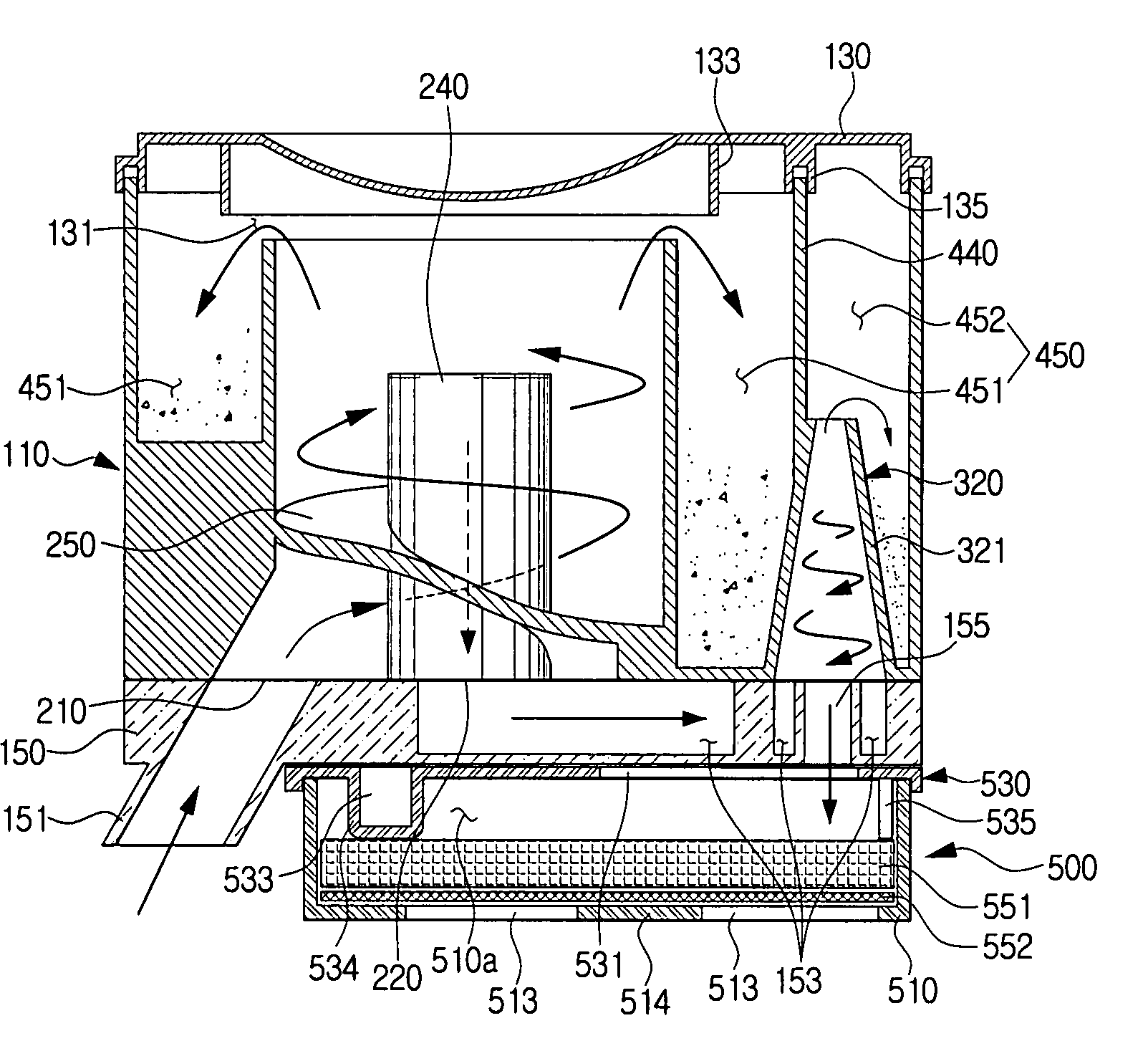
[0033]Referring to FIG. 1, a multi-cyclone dust separating apparatus 100 according to an embodiment of the present invention is shown. The multi-cyclone dust separating apparatus 100 is detachably attached to a main cleaner body 11 of a vacuum cleaner 1. The vacuum cleaner 1 may include a suction nozzle 2 to draw in dust from surface being cleaned, an extension pipe 3, a handle 5, a connecting hose 7, the main cleaner body 11, a suction motor 13 and a wheel 15. The main cleaner body 11 may have a dust collecting casing accommodating portion 11a and a seating space 11b.

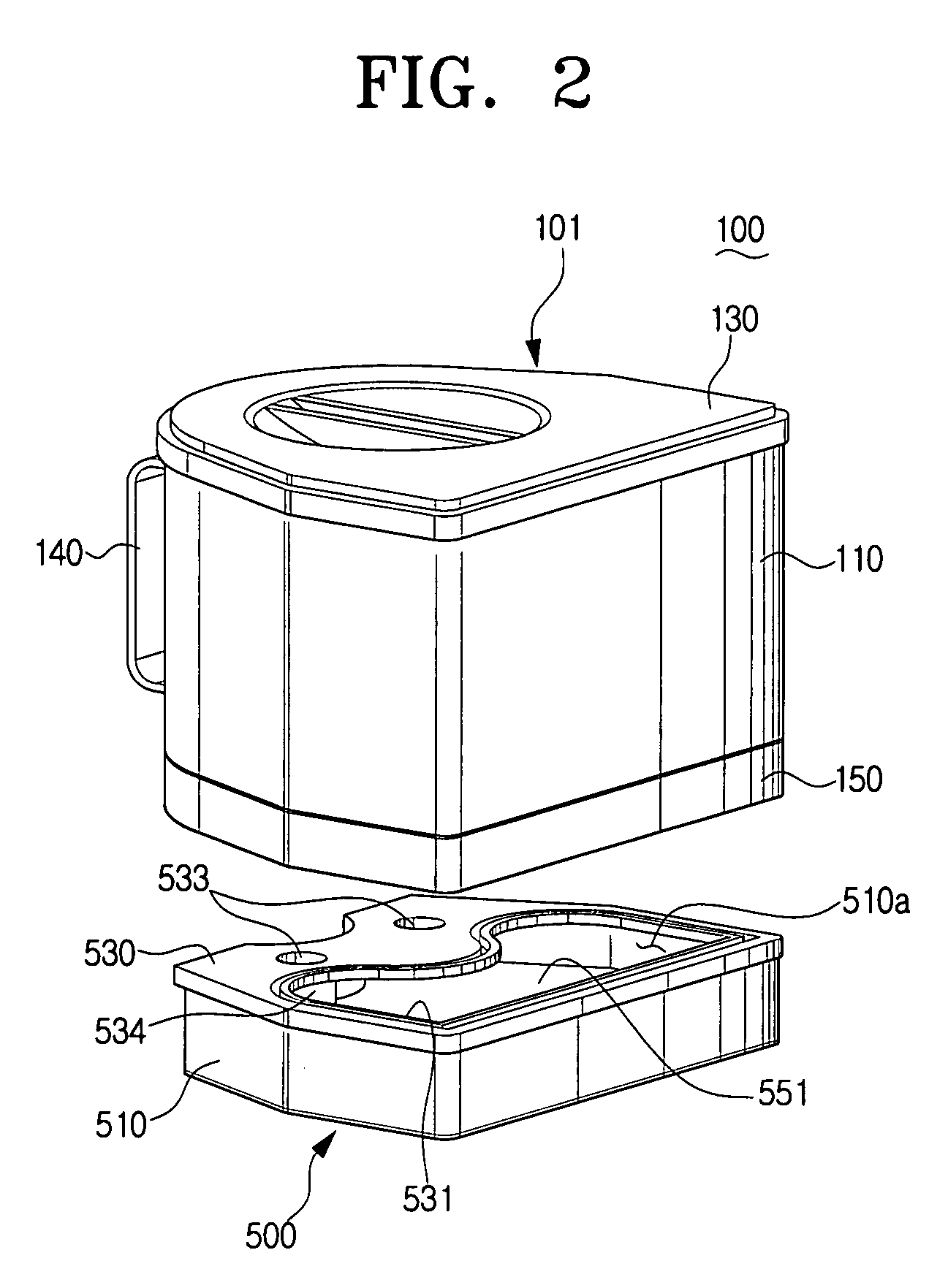
[0034]Referring to FIG. 2, the multi-cyclone dust separating apparatus 100 may include a cyclone unit 101 and a filter assembly 500. The cyclone unit 101 may include one or more of a cyclone bo...


PUM

PropertyMeasurementUnit
transparentaaaaaaaaaa
distanceaaaaaaaaaa
centrifugal forceaaaaaaaaaa

Abstract

A multi-cyclone dust separating apparatus includes a cyclone unit and a separable filter assembly adapted to be disposed at least partially in a discharge path of the cyclone unit. The cyclone unit includes a main cyclone, a secondary cyclone adapted to be disposed at substantially a same plane as the main cyclone, and a dust collecting casing adapted to substantially surround the main cyclone and the secondary cyclone. The dust collecting casing includes a dust chamber to collect dust separated at the main cyclone and the secondary cyclone.

Description

CROSS-REFERENCES TO RELATED APPLICATIONS[0001]This application claims the benefit of priority under 35 U.S.C. §119(a) from Korean Patent Application No. 2007-11670 filed on Feb. 5, 2007 in the Korean Intellectual Property Office, the disclosure of which is incorporated herein by reference in its entirety.[0002]This application may be related to the copending U.S. patent application Ser. No. 10 / 840,248, filed May 7, 2004 entitled “Cyclone Separating Apparatus and a Vacuum Cleaner Having the Same” by Jang-Keun Oh et al., the entire disclosure of which is incorporated herein by reference.[0003]This application may be related to the copending U.S. patent application Ser. No. 10 / 840,230, filed May 7, 2004 entitled “Cyclone Separating Apparatus and a Vacuum Cleaner Having the Same” by Jang-Keun Oh et al., the entire disclosure of which is incorporated herein by reference.[0004]This application may be related to the copending U.S. patent application Ser. No. 10 / 840,231, filed May 7, 2004 e...

Claims


Application Information

Patent Timeline
Patent Type & Authority Patents(United States)
IPC IPC(8): B01D45/12
CPCA47L9/122A47L9/1625A47L9/1641A47L9/1666Y10S55/03A47L9/16B04C9/00A47L9/10
Inventor OH, JANG-KEUNKIM, MIN-HA
Owner SAMSUNG GWANGJU ELECTRONICS CO LTD
Learn More