
Air/fuel imbalance monitor using an oxygen sensor

a technology of air/fuel imbalance and monitor, which is applied in the direction of electrical control, process and machine control, instruments, etc., can solve problems such as cylinder-cylinder air/fuel ratio imbalances, and achieve the effect of reliable imbalance indication

Active Publication Date: 2010-09-28
FORD GLOBAL TECH LLC
View PDF12 Cites 70 Cited by
  • Summary
  • Abstract
  • Description
  • Claims
  • Application Information

AI Technical Summary

Benefits of technology

This method effectively isolates and monitors air / fuel imbalances, even when sensor readings are confounded with exhaust gas from multiple cylinders, enabling accurate feedback control and reducing cylinder-to-cylinder variation.

Problems solved by technology

Applicants have recognized that cylinder-cylinder air / fuel ratio imbalances may occur due to cylinder-to-cylinder variation in intake valve depositions, plugged EGR orifices, and / or shifted fuel injectors.

Method used


Image

  • Air/fuel imbalance monitor using an oxygen sensor
  • Air/fuel imbalance monitor using an oxygen sensor
  • Air/fuel imbalance monitor using an oxygen sensor

Examples


Embodiment Construction

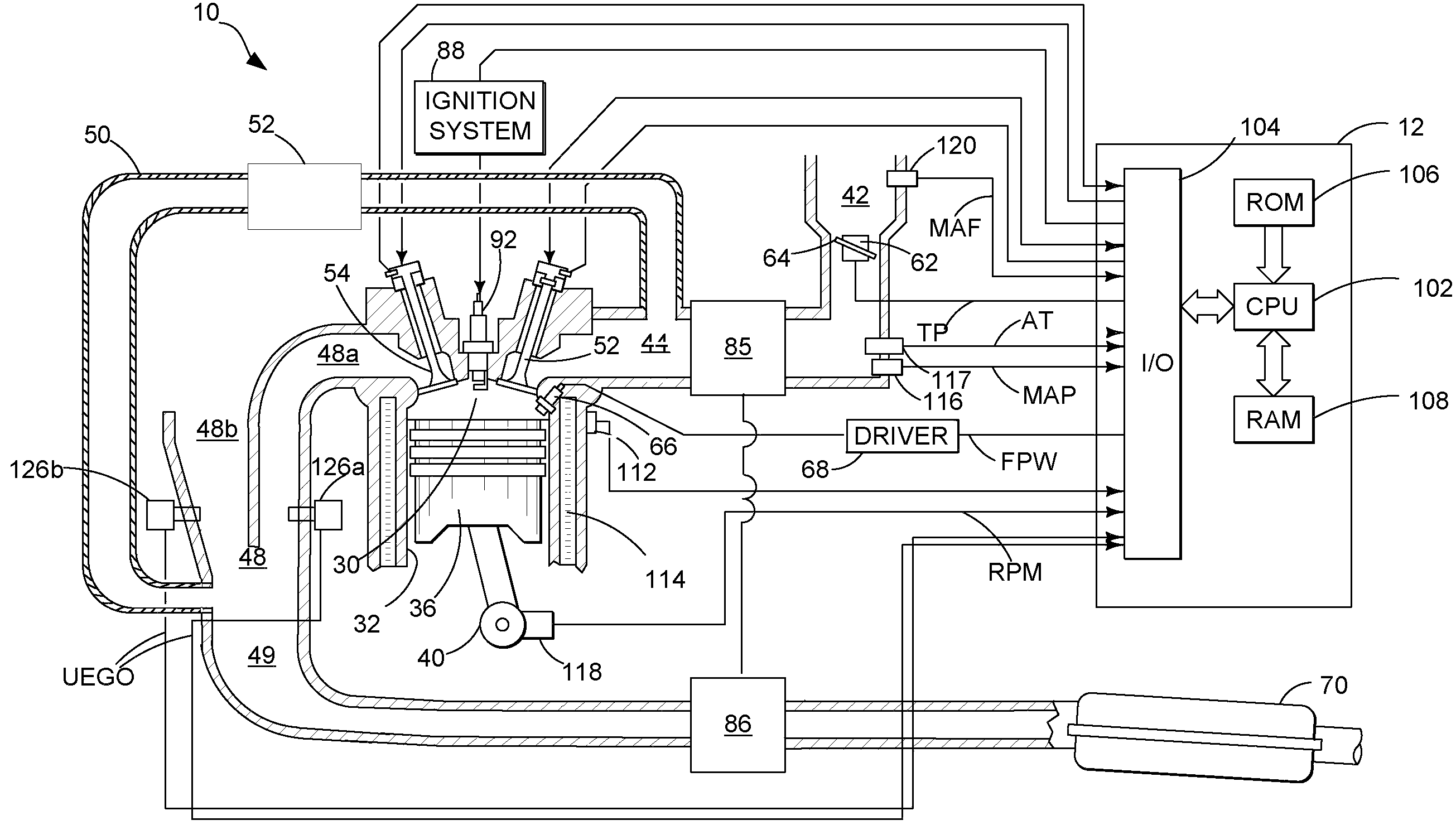
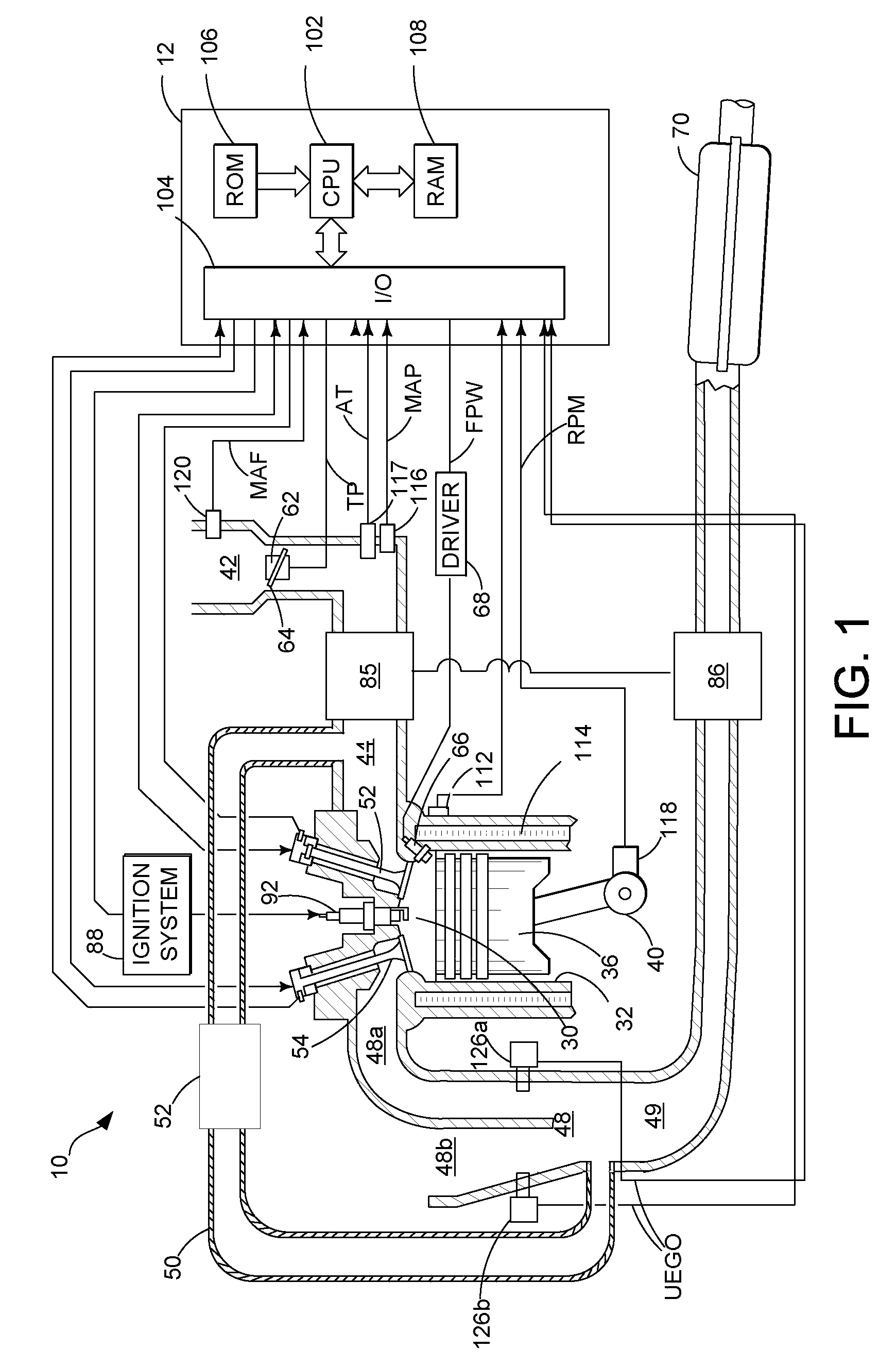
[0017]FIG. 1 is a schematic diagram of an example internal combustion engine 10 in which the disclosed system and method for monitoring air / fuel imbalance using an oxygen sensor, such as universal exhaust gas oxygen (UEGO) sensor or heated exhaust gas oxygen (HEGO) sensor, may be implemented. The engine 10 may be a diesel engine in one example and a gasoline engine in another example.

[0018]Engine 10 may comprise one or more engine cylinder banks (not shown), each of which may include a plurality of engine cylinders, only one cylinder of which is shown in FIG. 1. Engine 10 may include combustion chamber 30 and cylinder walls 32 with piston 36 positioned therein and connected to crankshaft 40. Combustion chamber 30 may communicate with intake manifold 44 and exhaust manifold 48 via respective intake valve 52 and exhaust valve 54. Engine 10 may be controlled by electronic engine controller 12.

[0019]Engine 10 is shown as a direct injection engine with injector 66 located to inject fuel ...


PUM


Abstract

Air / fuel imbalance monitoring systems and methods for monitoring air / fuel ratio imbalance of an internal combustion engine are disclosed. In one embodiment, an oxygen sensor is sampled above cylinder firing frequency and a ratio of data from at least one window over a total number of windows is determined. The approach can be used to indicate imbalances between engine cylinders.

Description

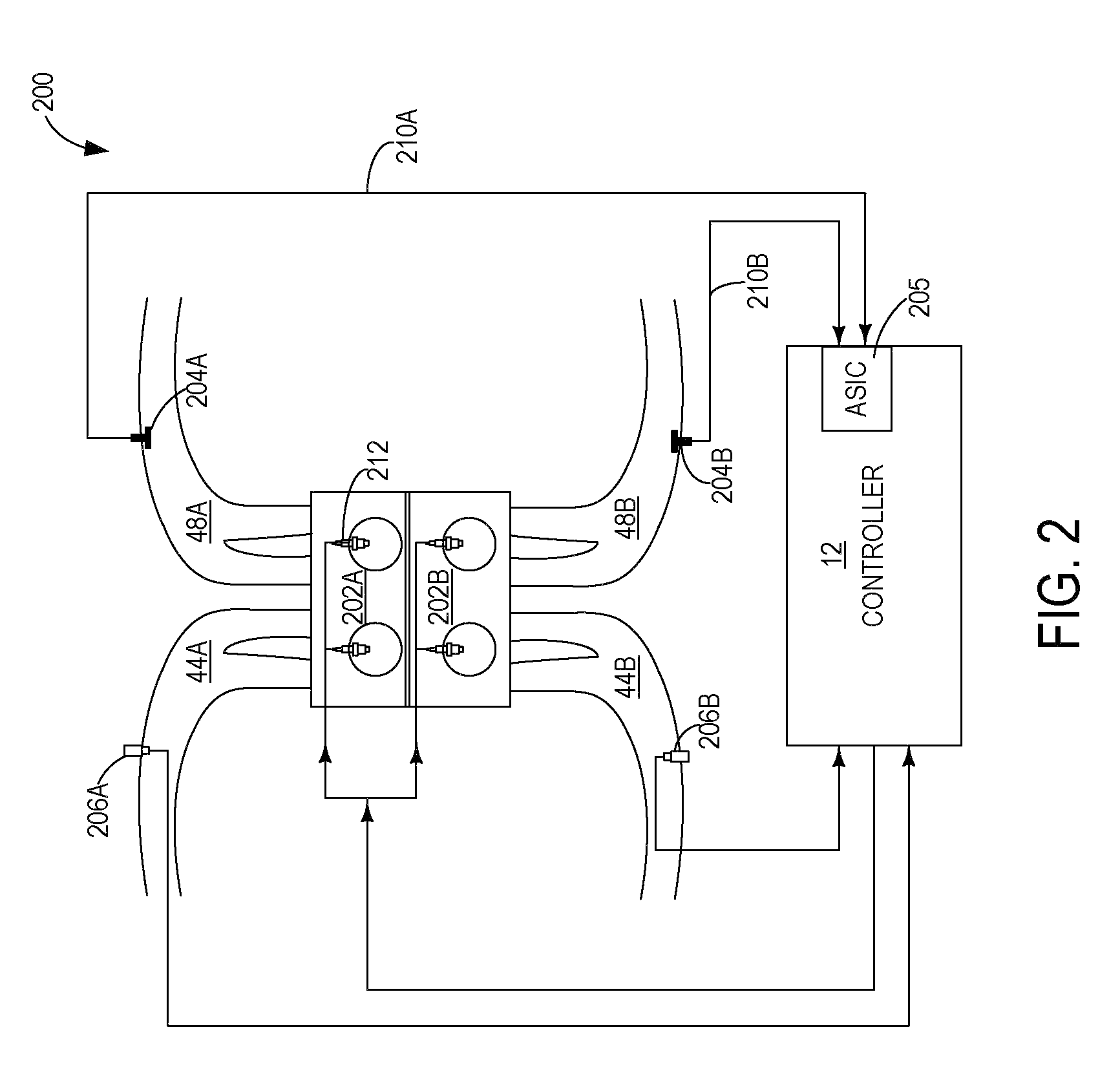
BACKGROUND AND SUMMARY[0001]Applicants have recognized that cylinder-cylinder air / fuel ratio imbalances may occur due to cylinder-to-cylinder variation in intake valve depositions, plugged EGR orifices, and / or shifted fuel injectors.[0002]While various approaches have been set forth for individual cylinder air-fuel control, with the aim at reducing cylinder-cylinder air-fuel ratio variation, such variation may persist. As such, air / fuel imbalance monitoring systems and methods for monitoring air / fuel ratio imbalance of an internal combustion engine having a plurality of engine cylinders are provided herein. An example of the method may include routing exhaust gas from a first group of cylinders to an exhaust gas oxygen sensor, and during selected operating conditions, indicating that air / fuel of at least one cylinder in the first group is imbalanced based on a response of the exhaust gas oxygen sensor at frequencies at or above firing frequency of the cylinders in the first group. A...

Claims


Application Information

Patent Timeline
Patent Type & Authority Patents(United States)
IPC IPC(8): F02D41/00F02D41/14
CPCF02D41/0082F02D41/1443F02D41/1456F02D41/0085F02D41/187
Inventor BEHR, KEN JOHNPATEL, HAS RKLUZNER, MICHAEL IGORJENTZ, BOB ROY
Owner FORD GLOBAL TECH LLC
Learn More