
Optical recording medium having physical and logical position information of buffer areas

a buffer area and optical recording technology, applied in the field of information recording mediums, can solve the problem that the read-only apparatus cannot read, and achieve the effect of efficient buffering area

Active Publication Date: 2010-09-21
PIONEER CORP
View PDF7 Cites 6 Cited by
  • Summary
  • Abstract
  • Description
  • Claims
  • Application Information

AI Technical Summary

Benefits of technology

[0006]With regard to such a two-layer type optical disc, a rewritable optical disc, such as a DVD-RW, is being developed. On the rewritable optical disc, a format process to make it in a data recordable condition is performed. Into an area set to be recorded by the format process, another data can be randomly overwritten. In a normal format process (normal format), a lead-in area and a lead-out area are formed, and a middle area is formed following the recorded data. By this, it is possible to substantially equalize the data structure of the rewritable optical disc, such as a DVD-RW, and the data structure of a read-only optical disc, such as a DVD-ROM.

Problems solved by technology

However, only one portion of the lead-in is recorded, and an area corresponding to the lead-out is not recorded, so that a read-only apparatus cannot read it.

Method used


Image

  • Optical recording medium having physical and logical position information of buffer areas
  • Optical recording medium having physical and logical position information of buffer areas
  • Optical recording medium having physical and logical position information of buffer areas

Examples


Embodiment Construction

[0101]Hereinafter, the best mode for carrying out the invention will be explained in order in each embodiment with reference to the drawings.

[0102](Information Recording Medium)

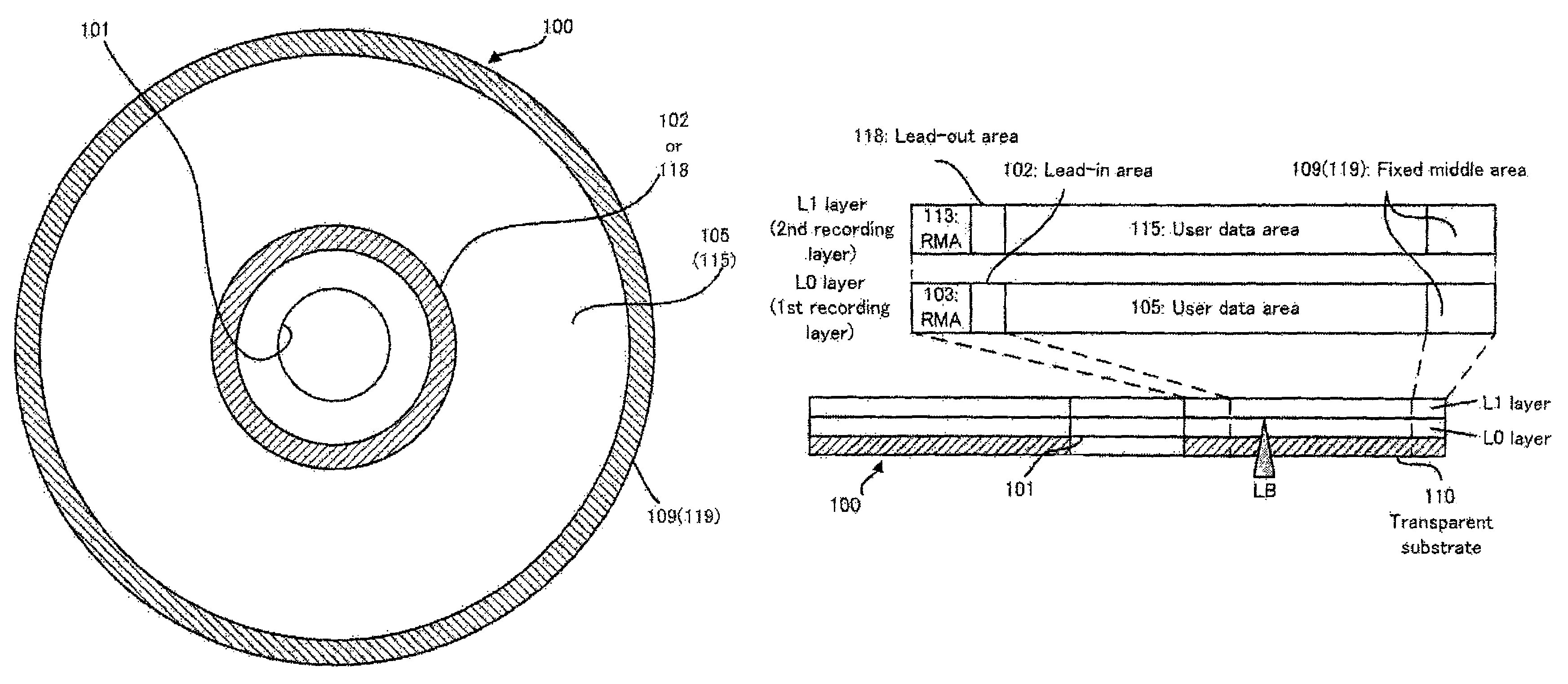
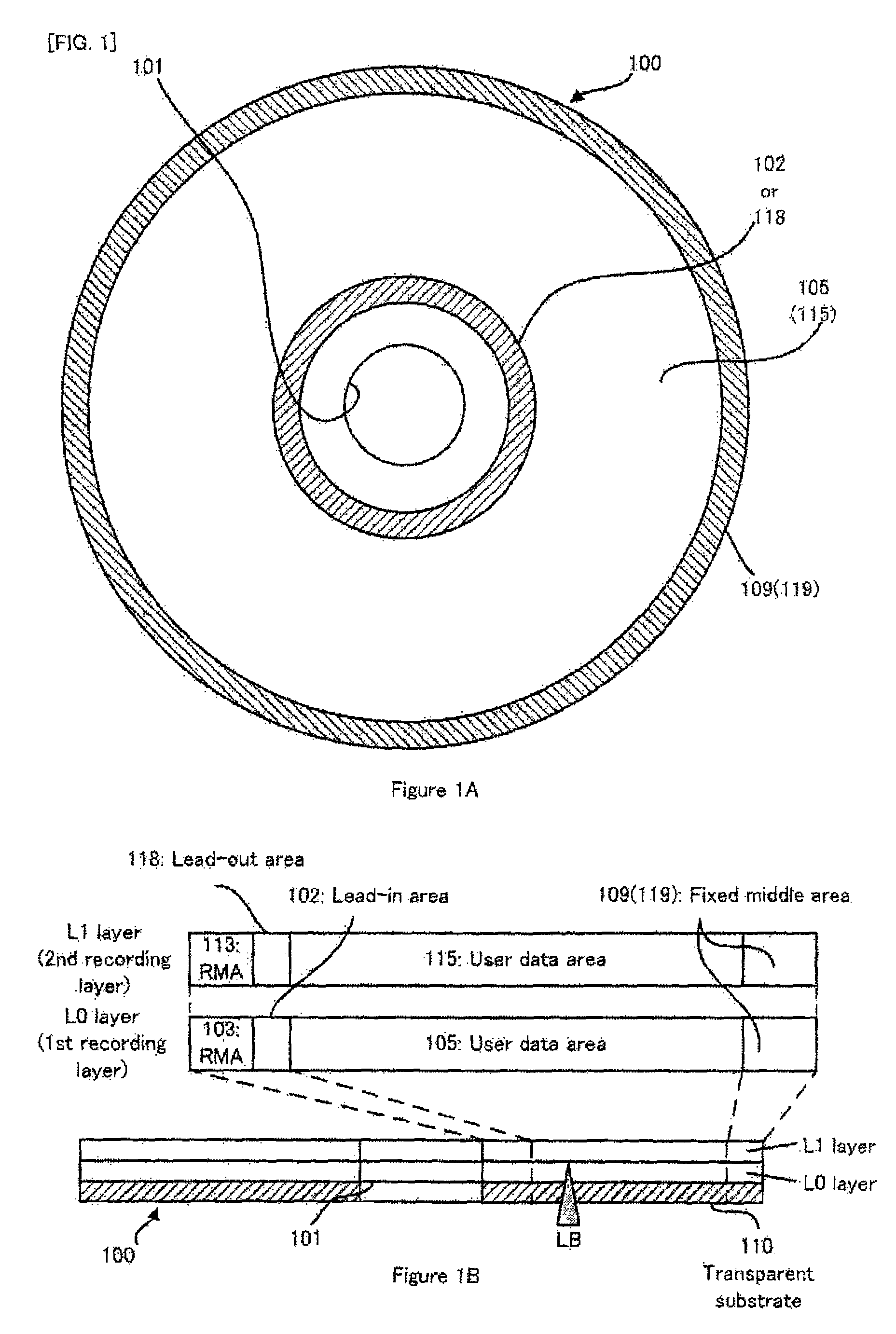
[0103]Firstly, with reference to FIG. 1, an optical disc 100 will be explained as an embodiment of the information recording medium of the present invention. FIG. 1(a) is a substantial plan view showing the basic structure of the optical disc 100 in the embodiment, and FIG. 1(b) is a schematic cross sectional view showing the optical disc 100 and its corresponding schematic conceptual view showing a recording area structure in the radial direction.

[0104]As shown in FIG. 1(a) and FIG. 1(b), the optical disc 100 has a recording surface on a disc main body with a diameter of about 12, cm, as is a DVD. On the recording surface, the optical disc 100 is provided with: a center hole 101 as the center; a lead-in area 102 or a lead-out area 118; user data areas 105 and 115; and fixed middle areas 109 and 119. Then, th...


PUM

PropertyMeasurementUnit
diameteraaaaaaaaaa
areaaaaaaaaaaa
compatibilityaaaaaaaaaa

Abstract

An optical disk (100) comprises recording management areas (103, 113) in which record management data for managing data recording is recorded. The record management data includes (i) physical position information (122, 125, 126) indicating the positions of physical buffer areas in which buffer data for buffering recording operation is physically recorded and (ii) logical position information (121) indicating the position of a logical buffer area in which buffer data is logically recorded or to be recorded.

Description

TECHNICAL FIELD[0001]The present invention relates to an information recording medium, such as a DVD (Digital Versatile Disc), an information recording apparatus and an information recording method, such as a DVD recorder, and a computer program which makes a computer function as such an information recording apparatus.BACKGROUND ART[0002]In an information recording medium, such as a DVD-ROM (DVD-Read Only Memory), a DVD-R (DVD-Recordable), and a BD-ROM (Blu-ray Disc-ROM), for example, as described in patent documents 1, and 2, etc., there is also developed an information recording medium, such as an optical disc, of a multilayer type or dual layer type, in which a plurality of recording layers are laminated or stacked on the same substrate. Then, if recording is performed with respect to a DVD-R of the dual layer type, i.e., of a two-layer type, out of the two-layer type optical disc, an information recording apparatus, such as a DVD recorder, focuses laser light for recording on a...

Claims


Application Information

Patent Timeline
Patent Type & Authority Patents(United States)
IPC IPC(8): G11B7/24
CPCG11B20/1217G11B27/329G11B2020/10861G11B2020/1235G11B2020/1267G11B2020/1277G11B2020/1278G11B2220/235
Inventor YOSHIDA, MASAYOSHIKATATA, KEIJIKODA, TAKESHITANIGUCHI, SHOJIMURAMATSU, EIJIKATO, MASAHIROMIURA, MASAHIROHASEBE, TSUYOSHI
Owner PIONEER CORP
Learn More