
Electrical connector with two-piece configured housing

a configuration housing and electric connector technology, applied in the direction of coupling device details, coupling device connections, electric discharge lamps, etc., can solve the problem of inconvenient manufacturing of electrical connectors, and achieve the effect of convenient sealing and preventing short circui

Inactive Publication Date: 2010-09-21
HON HAI PRECISION IND CO LTD
View PDF6 Cites 8 Cited by
  • Summary
  • Abstract
  • Description
  • Claims
  • Application Information

AI Technical Summary

Benefits of technology

[0007]Accordingly, the object of the present invention is to provide an electrical connector with a two-piece housing for soldering conveniently and preventing short circuit.

Problems solved by technology

It's difficult to solder the contact with a corresponding wire automatically, in manual soldering process, additional tubes are needed to prevent short circuit, so it's inconvenient for manufacturing the electrical connector.

Method used


Image

  • Electrical connector with two-piece configured housing
  • Electrical connector with two-piece configured housing
  • Electrical connector with two-piece configured housing

Examples


Embodiment Construction

[0016]Reference will now be made to the drawing figures to describe the present invention in detail.

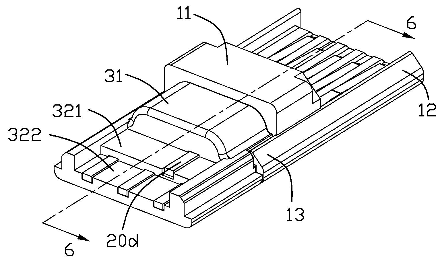
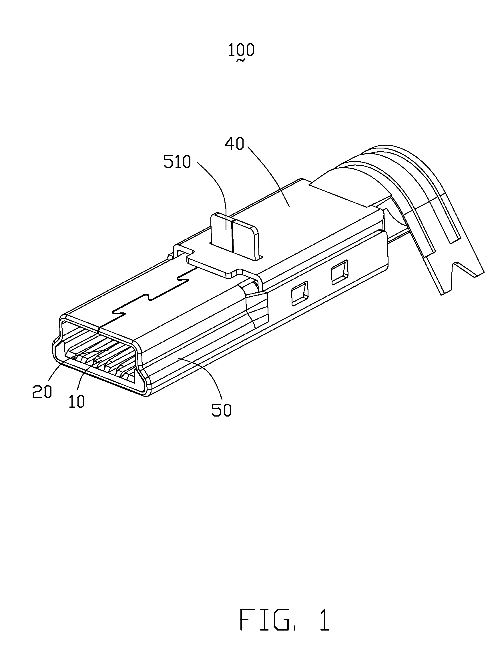
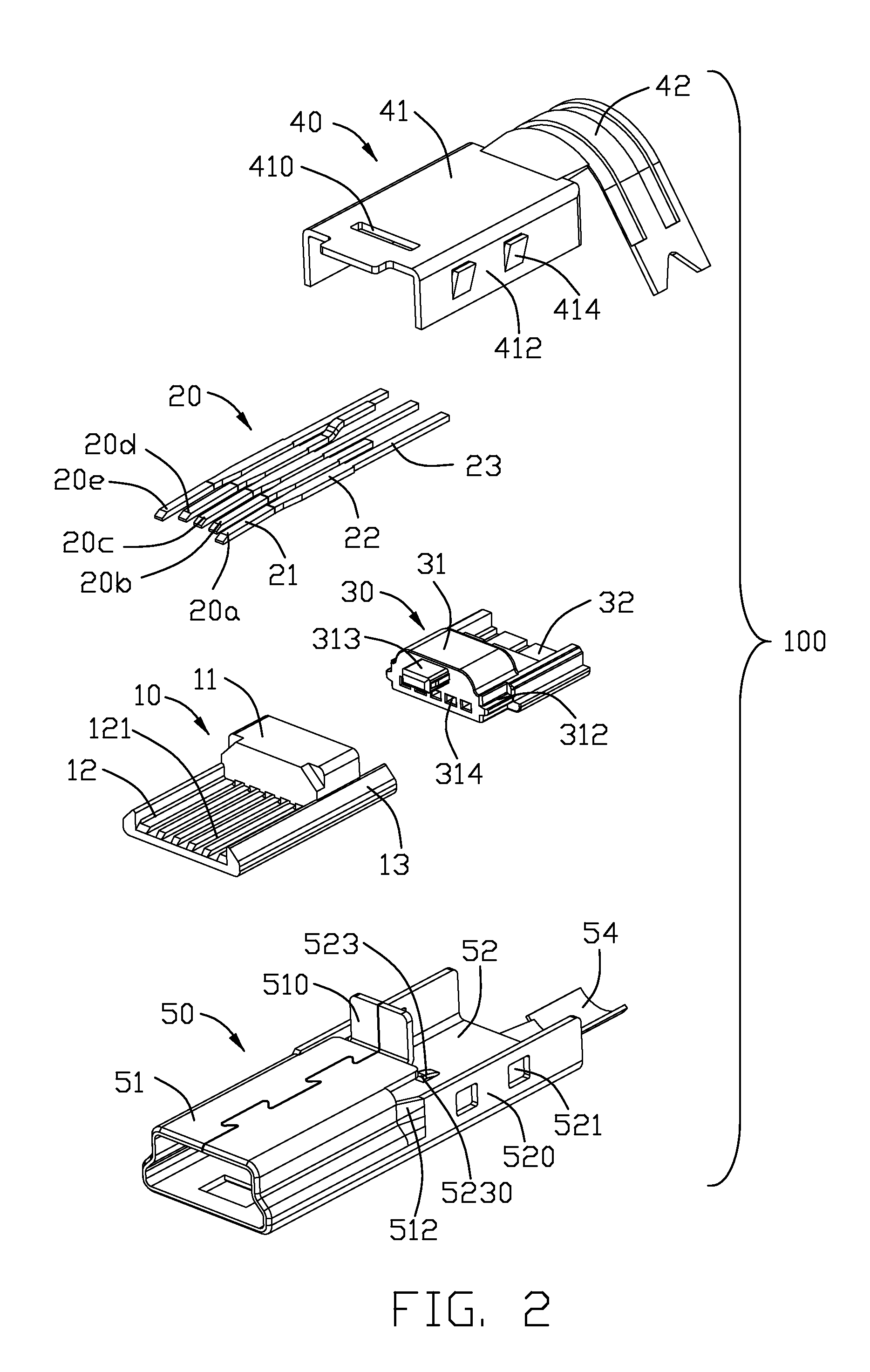
[0017]Referring to FIGS. 1-2, an electrical connector 100 in accordance with the present invention comprises a first housing 10, a contact set 20 inserted into the first housing 10, a second housing 30 assembled to the first housing 10 for supporting tail portions 23 of the contact set 20, a bottom shell 50 enclosing the first housing 10 and a top shell 40 assembled to a back portion of the bottom shell 50 along a up-to-down direction.

[0018]Referring to FIGS. 2-3, the first housing 10 is made of insulative material, and comprises a base portion 11, a U-shape tongue 12 extending forwardly from the base portion 11 along a mating direction and a pair of arms 13 extending rearwards from the base portion 11. The arms 13 respectively define a leading slot 131, and the pair of leading slots 131 are opposite to each other. A plurality of passageways 121 are defined in the tongue 12, the passa...


PUM


Abstract

An electrical connector (100) comprises a first insulative housing (10), a second insulative housing (30) engaging with the first insulative housing (10), and a plurality of contacts. Said second insulative housing (30) has a first platform (321) and a second platform (322) arranged at different levels. Each of the contacts (20) includes a mating portion (21) supported by the first insulative housing and a tail portion (23) supported by the second insulative housing, the tail portions (23) of the contacts are spaced into two rows and located on the first and second platforms; another contact has a tail portion disposed inside the second insulative housing.

Description

BACKGROUND OF THE INVENTION[0001]1. Field of the Invention[0002]The present invention generally relates to an electrical connector, and more particularly to an electrical connector with a two-piece configured housing.[0003]2. Description of Related Art[0004]Nowadays, miniaturization of electronic devices, such as notebooks, PDA, etc has become a trend such that the dimension and size of electronic connectors used therein have to be modified and reduced so as to meet the requirements.[0005]A typical electrical connector comprises an insulative housing, a group of contacts received in the housing and a metal shielding assembled to the housing. Each contact defines a tail portion exposed beyond the insulative housing. It's difficult to solder the contact with a corresponding wire automatically, in manual soldering process, additional tubes are needed to prevent short circuit, so it's inconvenient for manufacturing the electrical connector.[0006]Hence, it is desirable to have an improve...

Claims


Application Information

Patent Timeline
Patent Type & Authority Patents(United States)
IPC IPC(8): H01R24/00
CPCH01R9/032H01R13/506H01R13/65912
Inventor LIU, SU-FENGLAI, CHIN-TEYUAN, XIN
Owner HON HAI PRECISION IND CO LTD
Learn More