
Voltage regulator with reduced sensitivity of output voltage to change in load current

a voltage regulator and load current technology, applied in the field of integrated circuits containing voltage regulators, can solve the problems of affecting the ability to accurately sense the state of the memory element, the load current on the voltage regulator changes very quickly, and the voltage regulator may have difficulty maintaining the voltage at a target level, so as to prevent the voltage ripple and settle down relatively quickly

Active Publication Date: 2010-09-14
SANDISK TECH LLC
View PDF7 Cites 8 Cited by
  • Summary
  • Abstract
  • Description
  • Claims
  • Application Information

AI Technical Summary

Benefits of technology

The solution allows for quick settling of the output voltage during read operations of non-volatile storage elements, ensuring accurate sensing without the need for additional power-consuming components, thus improving the efficiency and accuracy of memory element state determination.

Problems solved by technology

One problem with voltage regulators is that if the load changes, the voltage regulator may have difficulty maintaining the voltage at a target level.
However, under some circumstances the load current on the voltage regulator changes very rapidly.
Unfortunately, this voltage ripple interferes with the ability to accurately sense the state of the memory element.
However, this capacitive current may lead to an error when comparing a reference current with the memory element current.
However, this adds to the time needed to sense the state of the memory elements.
However, the amplifier that is needed to adequately reduce the voltage ripple needs to be a fast amplifier that consumes considerable power to eliminate the voltage ripple.

Method used


Image

  • Voltage regulator with reduced sensitivity of output voltage to change in load current
  • Voltage regulator with reduced sensitivity of output voltage to change in load current
  • Voltage regulator with reduced sensitivity of output voltage to change in load current

Examples


Embodiment Construction

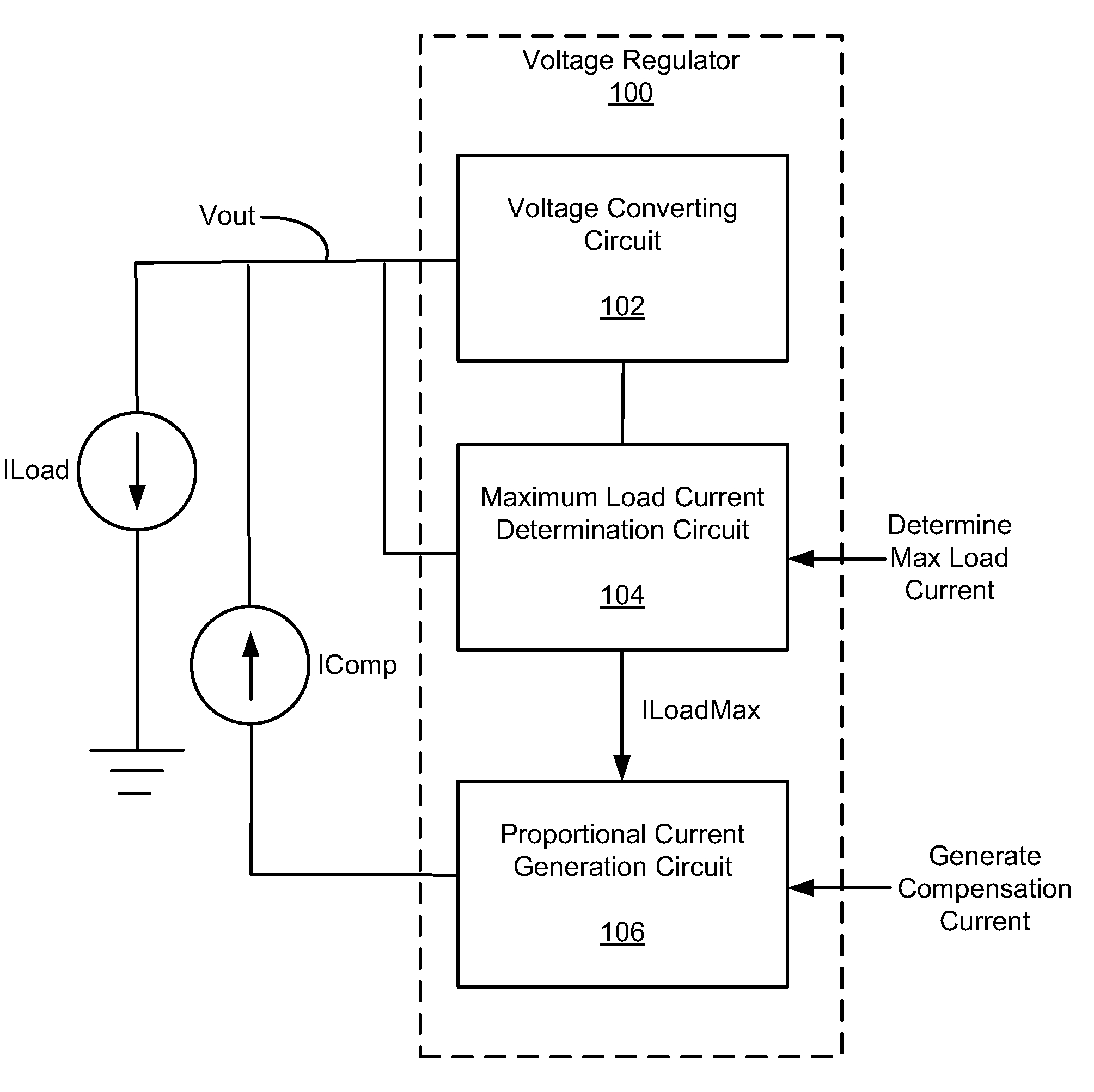
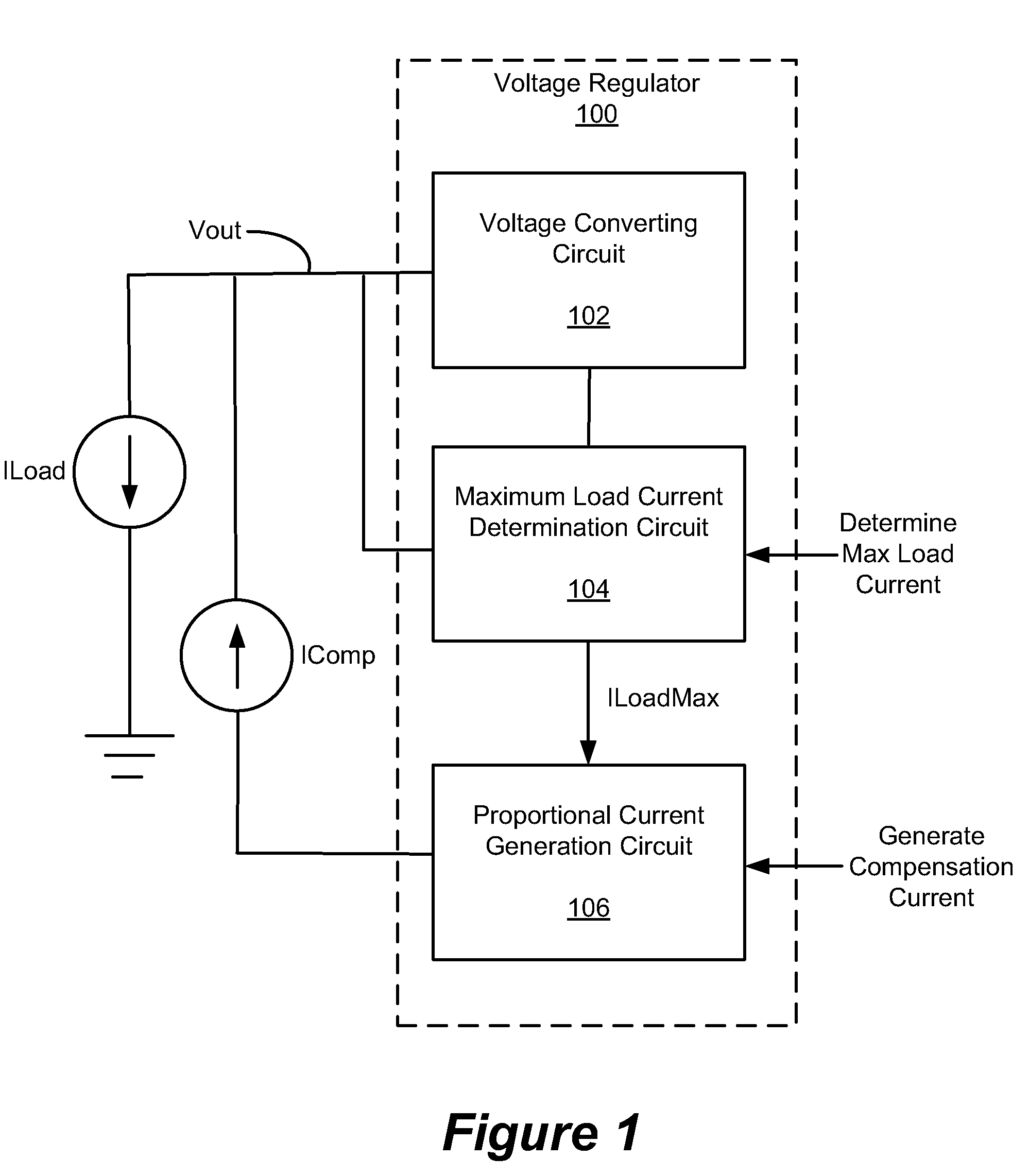
[0026]FIG. 1 depicts a block diagram of one embodiment of a voltage regulator 100. In general, the voltage regulator 100 includes a voltage converting circuit 102, a maximum load current determination circuit 104, and a proportional current generation circuit 106. In some embodiments, the voltage regulator 100 is used in a non-volatile storage device. Specifically, the voltage regulator 100 may be used to provide a regulated voltage to memory elements during a read (or sense) operation.

[0027]The voltage converting circuit 102 provides a regulated voltage “VOUT” to a load (e.g., memory element). The voltage converting circuit 102 provides a load current “ILOAD” that depends on the characteristics (e.g., impedance) of the load. Thus, if the impedance of the load changes, the load current will change. For example, if a switch closes to connect the voltage regulator 100 to memory elements to charge them to a known voltage prior to reading the memory elements, the load abruptly changes. ...


PUM


Abstract

A voltage regulator is disclosed. The voltage regulator has a voltage generation circuit that outputs a regulated voltage and a load current. The voltage regulation circuit has a sensing circuit that senses a peak magnitude of the load current and stores a peak signal that is based on the peak load current magnitude. The sensing circuit receives at least one signal that is input to the voltage regulation circuit and senses the peak magnitude of the load current. The voltage regulation circuit has a current generation circuit that generates a compensation current that has a magnitude that is proportional to the peak load current magnitude. The current generation circuit generates the compensation current based on the peak signal. The compensation current is provided during a time interval that is defined by at least one signal that is input to the voltage regulation circuit.

Description

BACKGROUND OF THE INVENTION[0001]1. Field of the Invention[0002]Embodiments in accordance with the present disclosure are directed to integrated circuits containing voltage regulators.[0003]2. Description of the Related Art[0004]A voltage regulator is an electronic circuit that provides a regulated voltage to a load. One problem with voltage regulators is that if the load changes, the voltage regulator may have difficulty maintaining the voltage at a target level. For purposes of illustration, the following example is provided of the difficulties that can occur when using a voltage regulator to supply voltages to a memory array of non-volatile storage elements. In the following example, the non-volatile storage elements are of a variety that store information based on a detectable change in state (state change elements).[0005]Materials having a detectable level of change in state, such as a resistance or phase change, are used to form various types of non-volatile semiconductor base...

Claims


Application Information

Patent Timeline
Patent Type & Authority Patents(United States)
IPC IPC(8): G11C16/06
CPCG11C5/147G11C16/30
Inventor CAZZANIGA, MARCO
Owner SANDISK TECH LLC
Learn More