
Linear motor automatic control circuit assembly for controlling the operation of a 3-phase linear motor-driven submersible oil pump of an artificial oil lift system

a technology of automatic control circuit and linear motor, which is applied in the direction of motor/generator/converter stopper, dynamo-electric converter control, instruments, etc., can solve the problems of inability to work with continuous pump speed adjustment, limited discrete stroke number adjustment, complicated pump speed adjustment,

Active Publication Date: 2010-09-14
WONG YEN HONG
View PDF2 Cites 69 Cited by
  • Summary
  • Abstract
  • Description
  • Claims
  • Application Information

AI Technical Summary

Benefits of technology

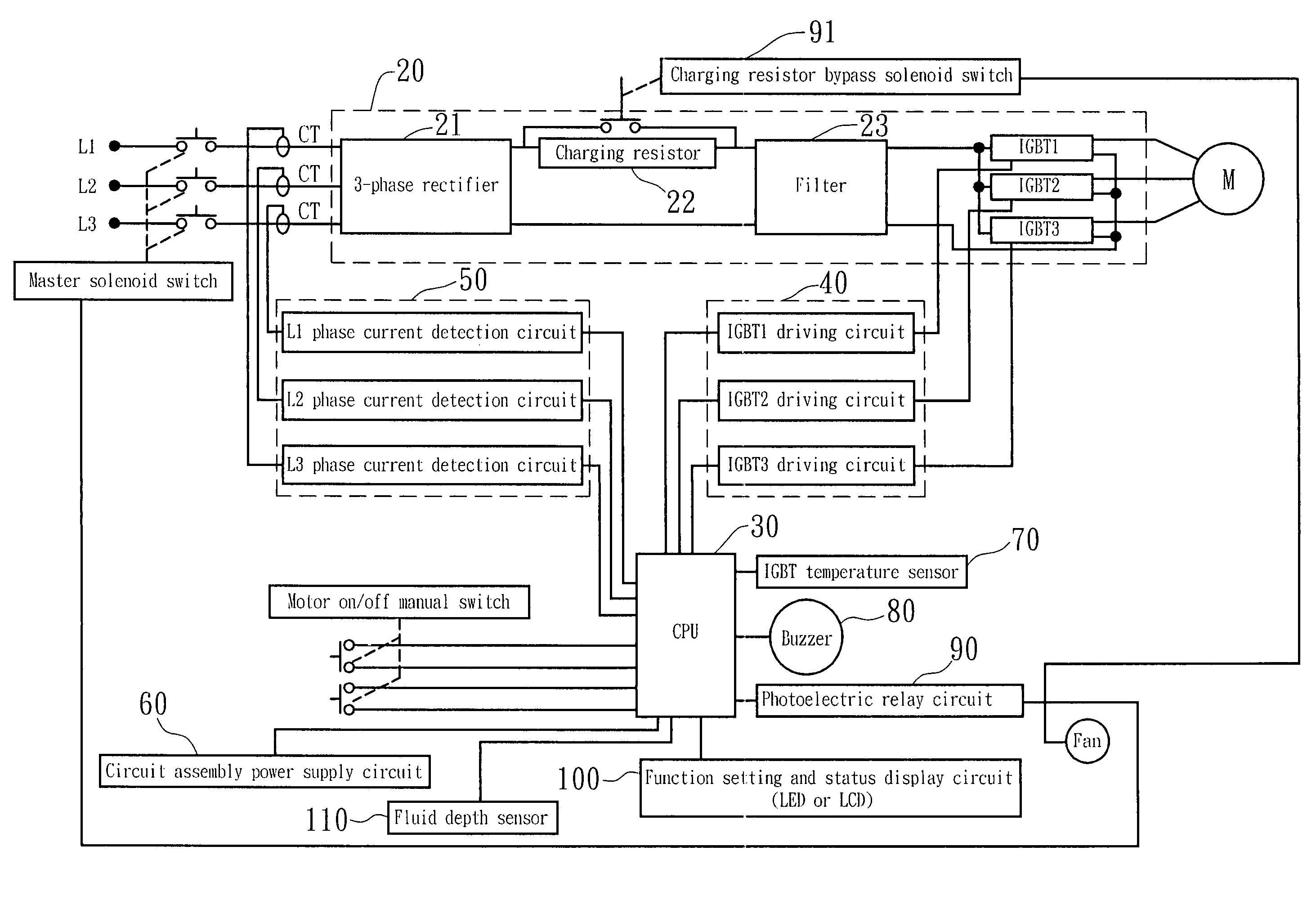
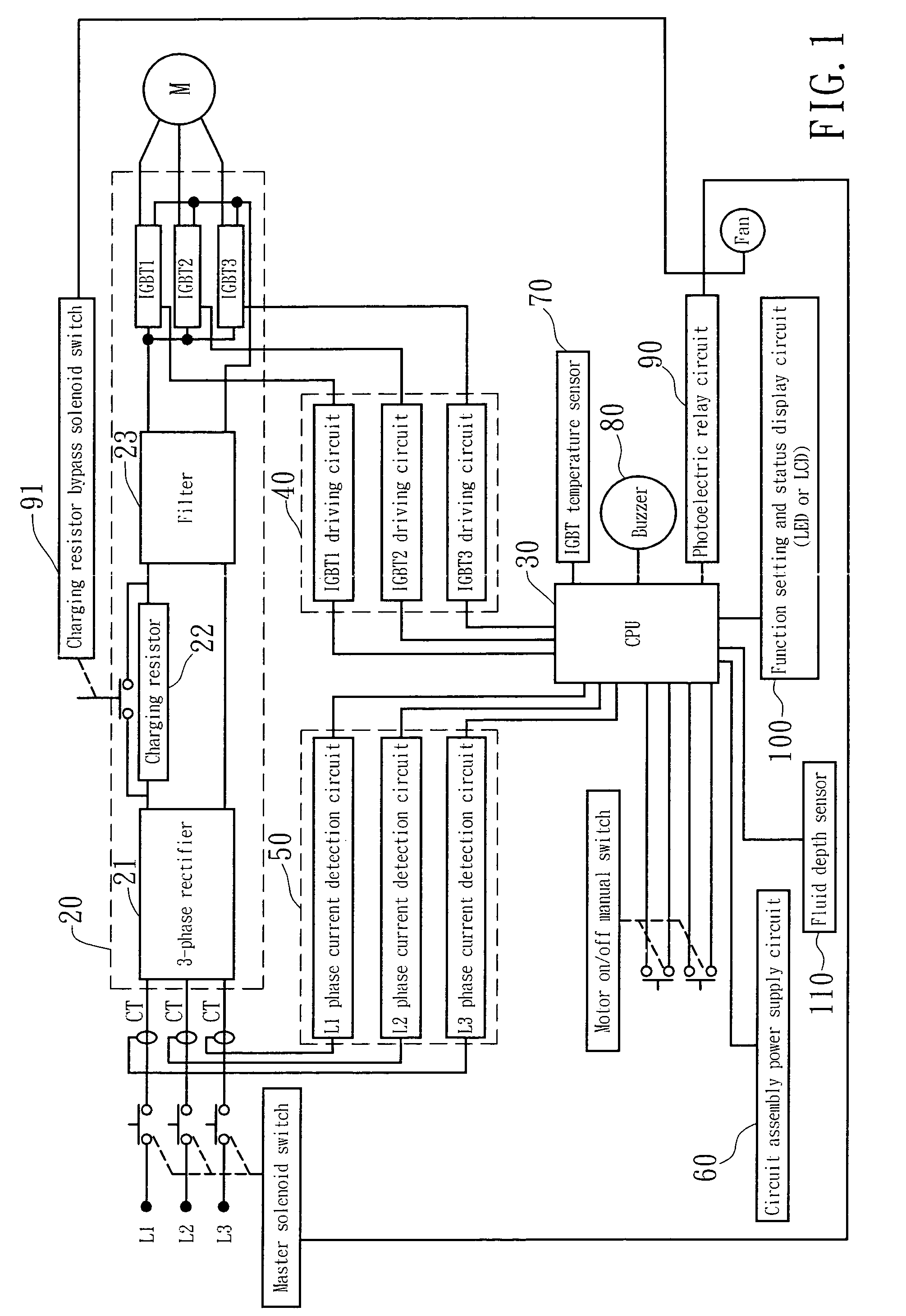
"The present invention provides a liner motor automatic control assembly for an artificial oil lift system that controls the operation speed of the linear motor based on the depth of the motor in the oil well. The assembly includes a power supply circuit, a CPU, an insulated gate bipolar transistor driving circuit, a current detection circuit, a fluid depth sensor, a function setting and status display circuit, and a circuit assembly power supply circuit. The power supply circuit provides power to the linear motor, the insulated gate bipolar transistor driving circuit controls the on, off, and speed of the motor, the current detection circuit detects the current value at the motor and provides it to the CPU for overcurrent protection control, and the fluid depth sensor detects the depth of the oil level in the well and provides it to the CPU for reference in controlling the motor's operation. The function setting and status display circuit sets system function parameters and displays the settings and the system's status. The circuit assembly power supply circuit provides the necessary working voltage for the control assembly."

Problems solved by technology

Further, the adjustment of the pump speed is complicated and limited to discrete stroke number adjustment.
A continuous pump speed adjustment is not workable.

Method used


Image

  • Linear motor automatic control circuit assembly for controlling the operation of a 3-phase linear motor-driven submersible oil pump of an artificial oil lift system
  • Linear motor automatic control circuit assembly for controlling the operation of a 3-phase linear motor-driven submersible oil pump of an artificial oil lift system
  • Linear motor automatic control circuit assembly for controlling the operation of a 3-phase linear motor-driven submersible oil pump of an artificial oil lift system

Examples


Embodiment Construction

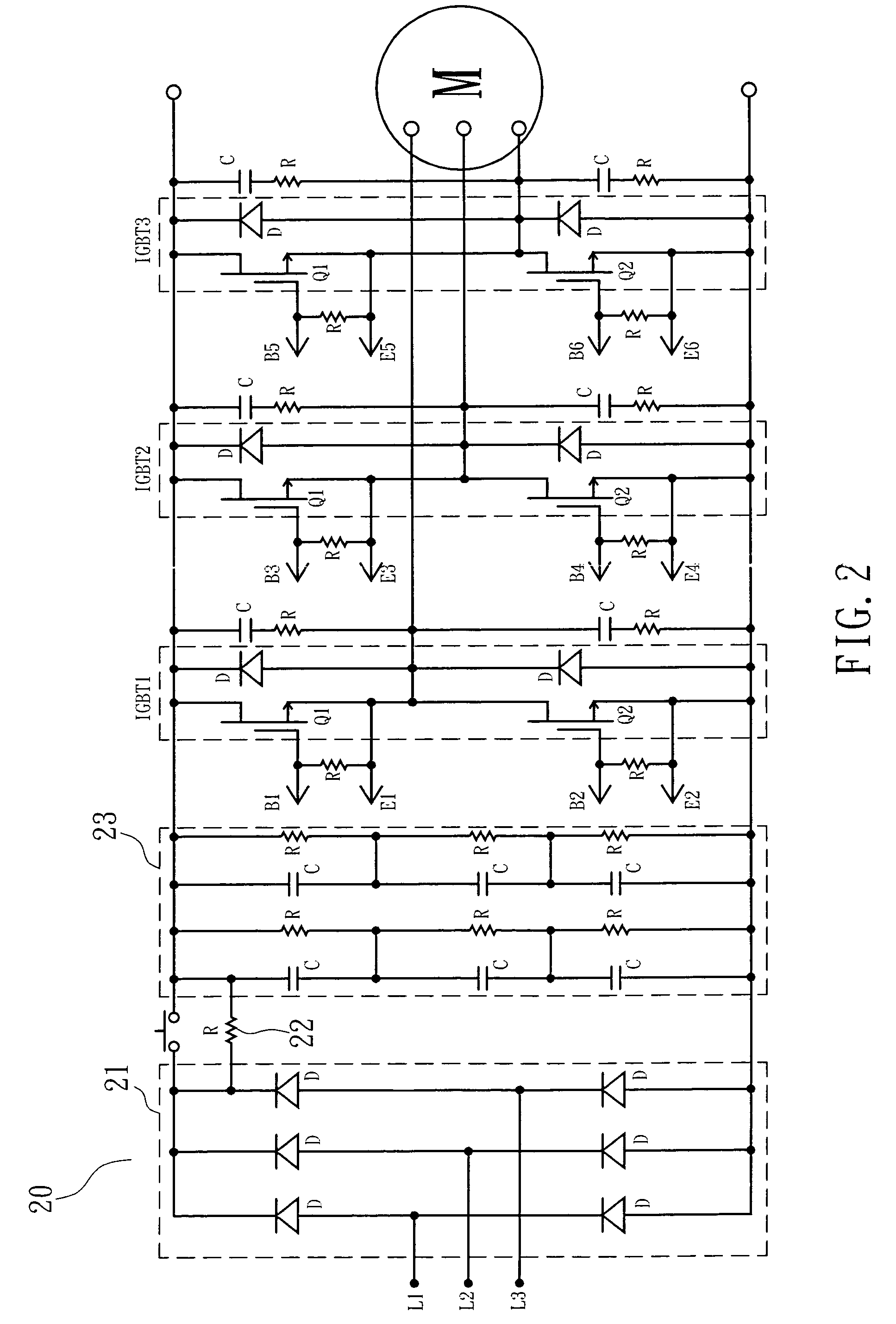
[0016]Referring to FIGS. 1˜8, a linear motor automatic control circuit assembly is connected to a 3-phase linear motor M that is adapted to drive a submersible oil pump of an artificial oil lift system. The linear motor automatic control circuit assembly comprises a linear motor power supply circuit 20, a CPU 30, an insulated gate bipolar transistor driving circuit 40, a current detection circuit 50, a fluid depth sensor 110, a function setting and status display circuit 100, and a circuit assembly power supply circuit 60. The linear motor power supply circuit 20 is comprised of a 3-phase rectifier 21, a charging resistor 22, a filter 23 and insulated gate bipolar transistors IGBT1, IGBT2 and IGBT3, and adapted to provide power supply to the linear motor M. The insulated gate bipolar transistor driving circuit 40 is electrically connected between the CPU 30 and the insulated gate bipolar transistors IGBT1, IGBT2 and IGBT3 of the linear motor power supply circuit 20, and adapted to c...


PUM


Abstract

Connected to a 3-phase linear motor of a submersible oil pump of a crude oil production system, a linear motor automatic control circuit assembly is disclosed to include a linear motor power supply circuit, a CPU, an insulated gate bipolar transistor driving circuit, a current detection circuit, a temperature sensor, a fluid depth sensor, a function setting and status display circuit, and a circuit assembly power supply circuit for controlling the operation speed of the linear motor subject to the submergence depth of the linear motor in the oil well.

Description

BACKGROUND OF THE INVENTION[0001]1. Field of the Invention[0002]The present invention relates to an artificial oil lift system and more specifically, to a linear motor automatic control circuit assembly for controlling the operation of a 3-phase linear motor-driven submersible oil pump of an artificial oil lift system.[0003]2. Description of the Related Art[0004]Beam / sucker-rod pumping is the most popular artificial lift in oil well for the production of crude oil today. A beam / sucker-rod pumping system has a submersible oil pump set in the oil well, and a rotary motor mounted on the ground to cause the walking beam to pivot up and down. The walking beam causes the sucker rod string attached to opposite end of the walking beam to rise and fall. This activates the submersible oil pump which lifts the oil up to the ground surface. The speed of the submersible oil pump that is installed in an oil well is adjustable by the worker at the ground. Further, the depth of the oil level in an ...

Claims


Application Information

Patent Timeline
Patent Type & Authority Patents(United States)
IPC IPC(8): H02K41/02H02P27/06
CPCF04B47/00
Inventor SHEN, KUEI-HSIENCHIANG, CHINN-CHANN
Owner WONG YEN HONG
Learn More