
Ink jet printing using a combination of non-marking and marking inks

a technology non-marking ink, which is applied in the field of ink jet printing, can solve the problems of limiting the paper that can be used, affecting and affecting the reliability of the digital printing engine, so as to achieve the effect of reducing the drying of the ink in the ink jet head and ensuring the quality of the paper

Inactive Publication Date: 2010-09-07
EASTMAN KODAK CO
View PDF6 Cites 8 Cited by
  • Summary
  • Abstract
  • Description
  • Claims
  • Application Information

AI Technical Summary

Benefits of technology

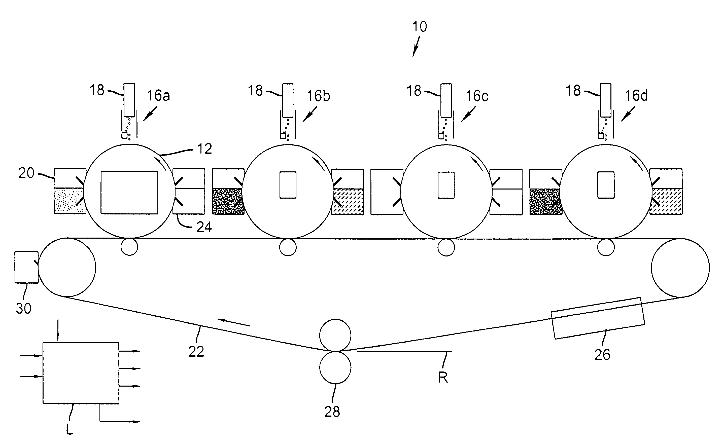
This patent describes a method for creating high-quality ink-based images using a non-marking ink and a marking ink with electrically charged particles. The process allows for the production of gray scale and high-density images using digital technology. By using non-marking ink, the same ink jet heads can be used for each color station, and the ink does not need to dry, resulting in a more reliable digital printing engine. The invention involves selectively ejecting droplets of non-marking liquid into cells of a printing member in a desired pattern, and then using marking ink to fill the cells and level them using a skive, roller, or other method. The ink is then transferred to a receiver, leaving predominantly clear liquid in the printing member cells. The invention provides a more efficient and reliable method for creating high-quality ink-based images.

Problems solved by technology

Although capable of high process speeds and excellent print quality, electrophotographic processes using dry or liquid toners are inherently complicated, and require expensive, large, complex equipment.
Moreover, due to their complex nature, electrophotographic processes and machines tend to require significant maintenance.
However, to avoid running and smearing of the ink droplets, the paper used in an ink jet printer must be porous, thereby restricting the papers that can be used and virtually eliminating the use of high quality graphic arts papers.
In addition, the absorption of the ink by the paper limits the density of the images that can be produced.
Finally, drying of ink requires a large amount of energy and would produce an inordinate amount of water or solvent vapors if used in high volume print engines.
However, dyes are subject to fading.
Pigments are more resistant to fading, but are particulate and tend to clog ink jet heads.
This however, results in larger ink droplets being formed, thereby reducing image resolution and quality.
Ink jet printing suffers from a number of drawbacks.
Ink jet printing is typically slower than traditional offset printing.
This represents a major issue limiting the implementation of ink jet technology in industrial printing systems.
This limits state of the art DOD ink jet printers to print rates on the order of 2 pages per second.
However, at high speeds, the results tend to be poor due to the difficulties mentioned above.
Another limitation of printing at high speed with ink jet technology arises from the amount of liquid used in ink jet printing.
Thus, the image on the receiver has relatively large amounts of ink, which need to be dried before the image is usable.
At high speeds, this drying step is complex and energy-intensive.
Ink jet printing currently cannot achieve printing quality as high as can be achieved using offset printing techniques.
Relatively small nozzle misalignments or off-center emission of droplets can cause banding.
These approaches reduce throughput of the printer.
This phenomenon leads to reduced quality printing, particularly on the grades of paper desirable in high-volume printing.
Wicking can cause printed dots to become much larger than the droplet of ink emerging from the ink jet nozzle.
Wicking can also reduce the brightness of the image, as the some of the colorant in the image gets wicked below the surface, thus not contributing adequately to image brightness.
However, such paper tends to be undesirably expensive.
As polymers do not absorb water or the carrier fluid of ink, the polymer layer has to incorporate voids or channels to “absorb” the relatively large amount of ink in a typically high-coverage pictorial image, which increases the cost and complexity of the receiver.
The matter of failure in ink jet nozzles is also deserving of attention.
Again, these usually have the effect of slowing down the net printing process speed.
This adds to the cost of the technology per printed page and again limits the industrial implementation of the technology.
Another important problem is the presence of fluid in the image.
None of these patents address the formation of a multi-color image.
While these patents address the problem of excess fluid in a four-color image, the process of registration of the component images from separate intermediates involve complex and expensive mechanisms.
The situation is further complicated if receivers of different thickness and / or surface properties need to be used.
In addition, the receiver path to accommodate successive transfers to form the multi-color image is relatively long, affecting cost and reliability.
Gravure printing is ideal for high run length printing applications, but is not generally suitable for shorter runs.
This is time consuming and expensive and must be amortized over many prints to yield suitable low cost prints.
Secondly, there is no way to ink the roller in a fashion that would enable it to print variable data, such as would be the case in digital printing.
This would create printing artifacts such as ghost images if the roller were used for variable data printing, unless the roller was first thoroughly cleaned.
Cleaning the gravure roller thoroughly is a difficult but necessary process since any trace amounts of ink remaining within a cell, normally inconsequential in conventional gravure printing because the same image is printed repeatedly, is quite detrimental to subsequent prints where variable data streams are involved.
Devices of this type may lead to image blurring from liquid coagulation, or dot placement errors and satellites from the ink jet device.
There is also a need to formulate separate pigmented inks for each color, leading to concerns about interactions between pigment particles and the ink jet print head since the ink jet device uses the different pigmented liquid for each color.

Method used


Image

  • Ink jet printing using a combination of non-marking and marking inks
  • Ink jet printing using a combination of non-marking and marking inks
  • Ink jet printing using a combination of non-marking and marking inks

Examples


Embodiment Construction

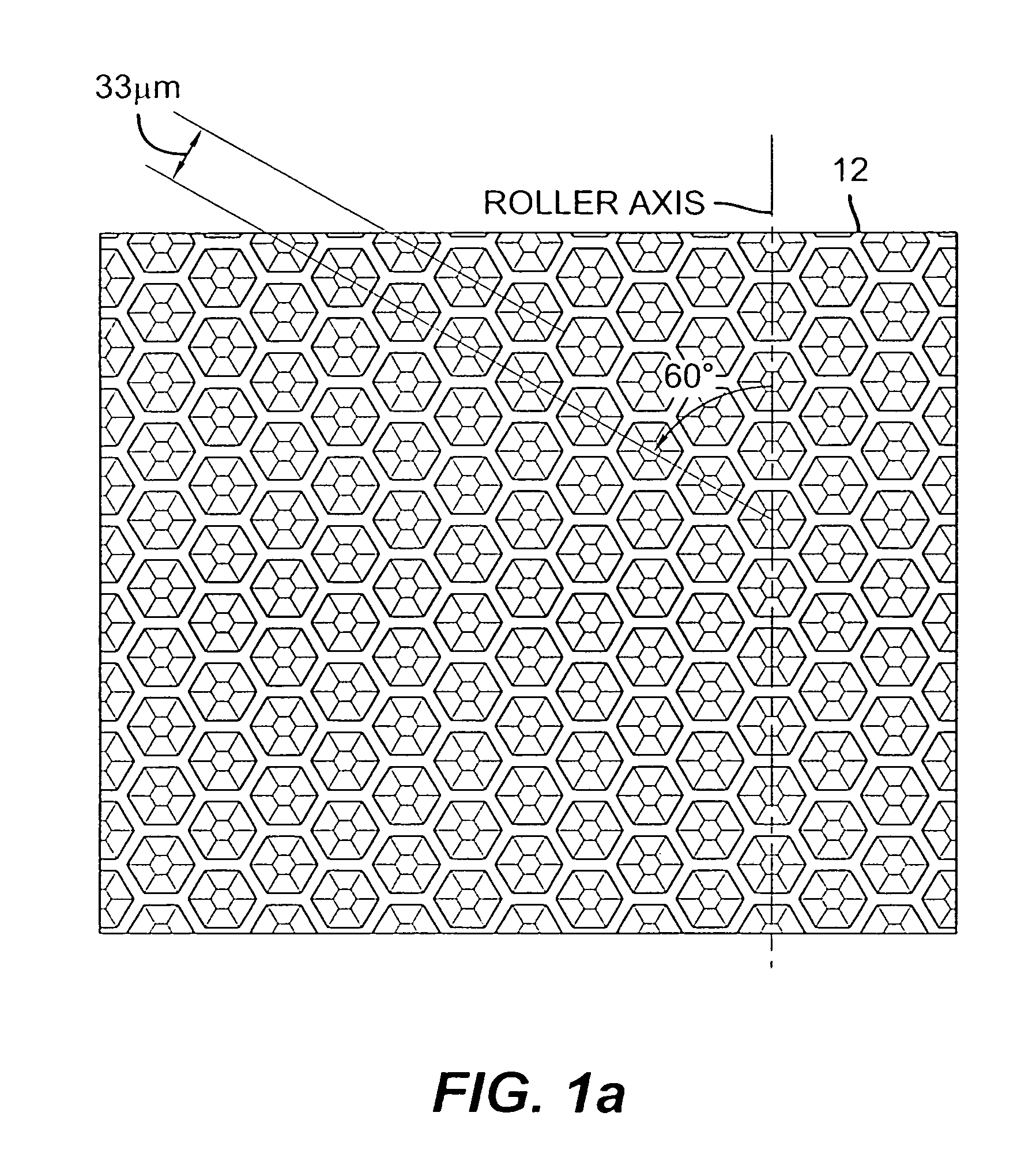
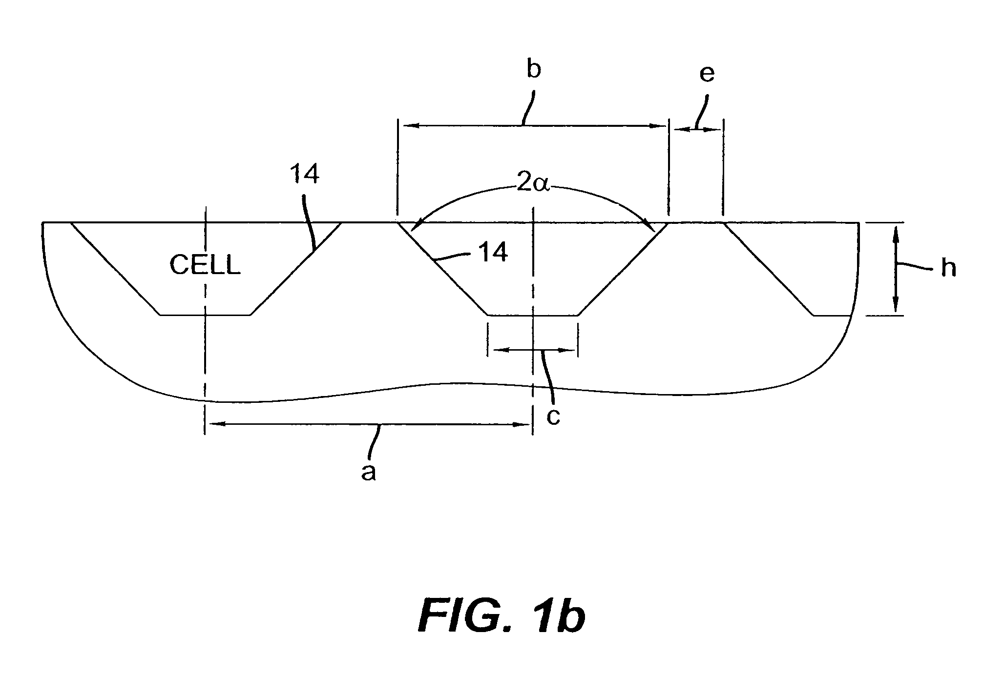
[0029]According to this invention, an ink jet mechanism is utilized to write an image, using a non-pigmented ink that is jetted into cells of a primary textured imaging member (TIM). The quantity of non-marking ink jetted into each cell varies, according to the negative image density of the image to be produced. Subsequent to the negative image-wise deposition of the non-marking ink, a marking ink of a chosen color is spread across the primary imaging member in such a manner as to fill the partially filled or unfilled cells of the TIM, thereby making a positive inked image. The preferred mode of filling the cells of the TIM with marking ink is to spread the ink using a roller, doctor blade, squeegee, or other known mechanism that is in intimate contact with the TIM, thereby forcing the marking ink into the partially filled or unfilled cells and skiving the ink off the TIM in all other areas.

[0030]In similar fashion, this technology can be used to produce digital binary images, i.e. ...


PUM


Abstract

An ink jet device selectively ejects droplets of non-marking liquid ink into cells of a printing member in a desired latent negative image pattern. Certain cells of the printing member are filled with pigmented ink to create a desired image. An electrical bias is applied for fractionating pigment in the pigmented ink from liquid and transferring an image-wise pigmented ink pattern from the printing member to a receiving member, leaving behind a substantial portion of liquid. The receiver can be an intermediate member whereby the image-wise ink pattern is transferred from the intermediate member to a final receiver, while such receiver is in operative association with said intermediate member.

Description

FIELD OF THE INVENTION[0001]This invention relates in general to ink jet printing, and more particularly to ink jet printing using a combination of non-marking and marking inks.BACKGROUND OF THE INVENTION[0002]High-resolution digital input imaging processes are desirable for superior quality printing applications, especially those requiring that changes be made from one print to the next or those where relatively short numbers of prints are to be made. As is well known, such processes may include electrostatographic processes using small-particle dry toners, e.g., having particle diameters less than about 7 micrometers, electrostatographic processes using solvent based liquid developers (also referred to as liquid toners) in which the particle size is typically on the order of 0.1 micrometer or less, and ink-jet processes using aqueous or solvent based inks.[0003]The most widely used high-resolution digital commercial electrostatographic processes involve electrophotography. Althoug...

Claims


Application Information

Patent Timeline
Patent Type & Authority Patents(United States)
IPC IPC(8): B41J2/01C09D11/00C09D11/30
CPCB41J2/0057B41J2/01
Inventor TOMBS, THOMAS NATHANIELRIMAI, DONALD SAULZEMAN, ROBERT EDWARD
Owner EASTMAN KODAK CO
Learn More