Pulse pattern generator and communication device evaluation system utilizing the same

a technology of communication device and pulse pattern, which is applied in the direction of single pulse train generator, transmission monitoring, instruments, etc., can solve the problem of reducing the productivity of the communication device production line, and achieve the effect of improving the reliability of the evaluation resul

Inactive Publication Date: 2010-08-31
ANRITSU CORP
View PDF13 Cites 15 Cited by
  • Summary
  • Abstract
  • Description
  • Claims
  • Application Information

AI Technical Summary

Benefits of technology

[0017]In view of the foregoing, an object of the present invention is to provide a pulse pattern generator which is improved so as to generate the pulse signal having the desired pulse pattern having the predetermined eye closure set by the pulse pattern generator in itself, and a communication device evaluation system in which the productivity can be increased by utilizing the improved pulse pattern generator for the communication device evaluation system to simplify the evaluation test for the device under test when compared with the conventional evaluation system.
[0086]Consequently, in the communication device evaluation system utilizing the pulse pattern generator according to the present invention, the pulse signal whose eye is opened or the pulse signal whose eye is not open can be supplied as a test signal from the pulse pattern generator to the device under test. Thus, the evaluation test for the device under test can be simplified to improve the productivity compared with the conventional evaluation system.
[0088]Accordingly, in the communication device evaluation system utilizing the pulse pattern generator according to the present invention, the device under test can be evaluated with the approximate pulse signal waveform for the pulse signal waveform which is actually transmitted in the telecommunication network, the optical communication network, and the like, so that the reliability of the evaluation result can be improved.

Problems solved by technology

Accordingly, in the conventional evaluation system for the communication device, a stress-test process performed in the production line of the communication device becomes remarkably complicated, and therefore, there is a problem that productivity is decreased in the production line of the communication device.

Method used


Image

  • Pulse pattern generator and communication device evaluation system utilizing the same
  • Pulse pattern generator and communication device evaluation system utilizing the same
  • Pulse pattern generator and communication device evaluation system utilizing the same

Examples


first embodiment

[0116]First, a configuration of a communication device evaluation system utilizing a pulse pattern generator according to a first embodiment of the present invention will be described below.

[0117]Explanation will be given for, as an example, a case where the communication device evaluation system utilizing the pulse pattern generator according to the first embodiment evaluates a device for use in telecommunication such as, for example, a transceiver and a router as a device under test (hereinafter referred to as “DUT”).

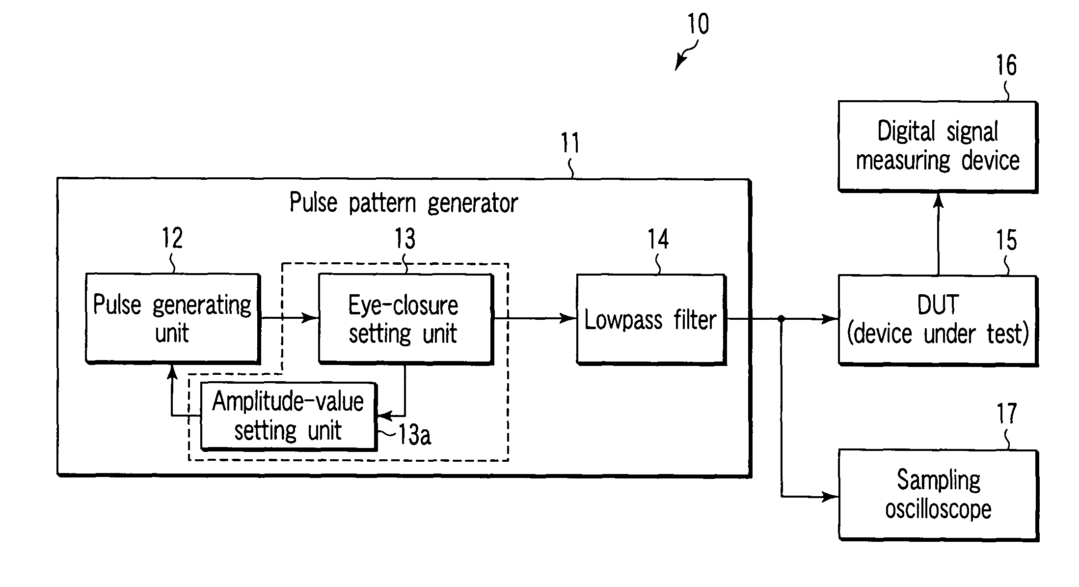
[0118]As shown in FIG. 1, a communication device evaluation system 10 utilizing the pulse pattern generator of the first embodiment includes: a pulse pattern generator 11 which generates a pulse signal; a digital signal measuring device 16 which measures characteristics of a DUT 15 serving as a communication device for used in telecommunication based on the pulse signal output from the pulse pattern generator 11; and a sampling oscilloscope 17 which monitors the pulse...

second embodiment

[0161]First, a configuration of a communication device evaluation system utilizing a pulse pattern generator according to a second embodiment of the invention will be described with reference to FIG. 7.

[0162]In this embodiment, explanation will be given for, as an example, a case where the communication device evaluation system utilizing the pulse pattern generator evaluates DUT such as an equalizer for converting a pulse signal whose eye closure is extremely low or a pulse signal whose eye is not opened into a pulse signal whose eye is opened.

[0163]However, the communication device evaluation system utilizing the pulse pattern generator of the second embodiment is one in which a modification is made to the pulse pattern generator 11 shown in FIG. 1 in the communication device evaluation system 10 utilizing the pulse pattern generator of the first embodiment of the invention, and other configurations thereof are similar to those of the communication device evaluation system 10.

[0164...

third embodiment

[0184]First, a configuration of a communication device evaluation system utilizing a pulse pattern generator according to a third embodiment of the invention will be described with reference to FIG. 9.

[0185]In the communication device evaluation system utilizing the pulse pattern generator according to the third embodiment, explanation will be given for a case where a device for use in optical communication, such as an optical transceiver and an optical transponder is evaluated as the DUT.

[0186]However, in FIG. 9, the same configuration as the communication device evaluation system 10 utilizing the pulse pattern generator according to the first embodiment of the invention is designated by the same numeral, and the detailed description will be omitted.

[0187]As shown in FIG. 9, a communication device evaluation system 40 utilizing the pulse pattern generator according to the third embodiment includes: the pulse pattern generator 11; an electric / optical converter (hereinafter referred ...


PUM


Abstract

A pulse pattern generator (11) has a pulse generating unit (12) and a lowpass filter (14), and the pulse generating unit (12) includes an amplitude-value setting unit (13, 13a). The pulse generating unit (12) generates a pulse signal formed in a step-like wave in which at least one of rise and fall of a signal is changed in a step-like manner. The lowpass filter (14) smoothes the pulse signal generated by the pulse generating unit (11), and outputs a smoothed pulse signal. The amplitude-value setting unit (13, 13a) adjusts an amplitude value of a step-like wave that forms the pulse signal in order to set a shape of an eye waveform based on a setting value when an eye pattern of the output from the lowpass filter (14) is formed. The pulse pattern generator (11) can output the pulse signal having a desired pulse pattern having the predetermined eye closure from the lowpass filter (14).

Description

[0001]This application is a U.S. National Phase Application under 35 USC 371 of International Application PCT / JP2005 / 012241 filed Jul. 1, 2005.TECHNICAL FIELD[0002]The present invention relates to a pulse pattern generator and a communication device evaluation system utilizing the same, and particularly, to a pulse pattern generator which generates a pulse signal having a desired pulse pattern for evaluating a communication device such as a telecommunication device and an optical communication device, and a communication device evaluation system utilizing the same.BACKGROUND ART[0003]As is well known, recently, demand for high-speed and large-capacity communication is increased as information communication represented by the Internet has rapidly grown.[0004]The demand also causes expansion of broadband communication with a telecommunication system or an optical communication system utilizing optical fibers.[0005]A digital communication method is adopted in the telecommunication syst...

Claims


Application Information

Patent Timeline
Patent Type & Authority Patents(United States)
IPC IPC(8): H04B14/04H03K3/78H04B3/04H04B10/07H04B10/079H04B10/2507H04B10/524H04B10/54
CPCG06F1/02H03K5/156G01R31/31928H03K4/02
Inventor YAMAGUCHI, KAZUHIKO
Owner ANRITSU CORP
Why Eureka
Try Eureka