
Cable management arrangement for a telecommunications cabinet

a technology for telecommunications cabinets and cable management, which is applied in the direction of machine supports, coupling device connections, instruments, etc., can solve the problems of difficult management of large slack lengths, and achieve the effect of improving cable accessibility

Inactive Publication Date: 2010-08-31
COMMSCOPE TECH LLC
View PDF17 Cites 37 Cited by
  • Summary
  • Abstract
  • Description
  • Claims
  • Application Information

AI Technical Summary

Benefits of technology

Enhances cable accessibility and organization, reducing the need for unwinding other cables to access a single cable, while protecting different types of cabling and maintaining their respective bend radii, thus simplifying maintenance and repair processes.

Problems solved by technology

With the vast number of cables, the mass of slack length can become difficult to manage; especially in circumstances where repair or maintenance of one cable, buried well beneath the wound loops of other cable slack lengths, is required.

Method used


Image

  • Cable management arrangement for a telecommunications cabinet
  • Cable management arrangement for a telecommunications cabinet
  • Cable management arrangement for a telecommunications cabinet

Examples


Embodiment Construction

[0022]Reference will now be made in detail to exemplary aspects of the present disclosure that are illustrated in the accompanying drawings. Wherever possible, the same reference numbers will be used throughout the drawings to refer to the same or like parts.

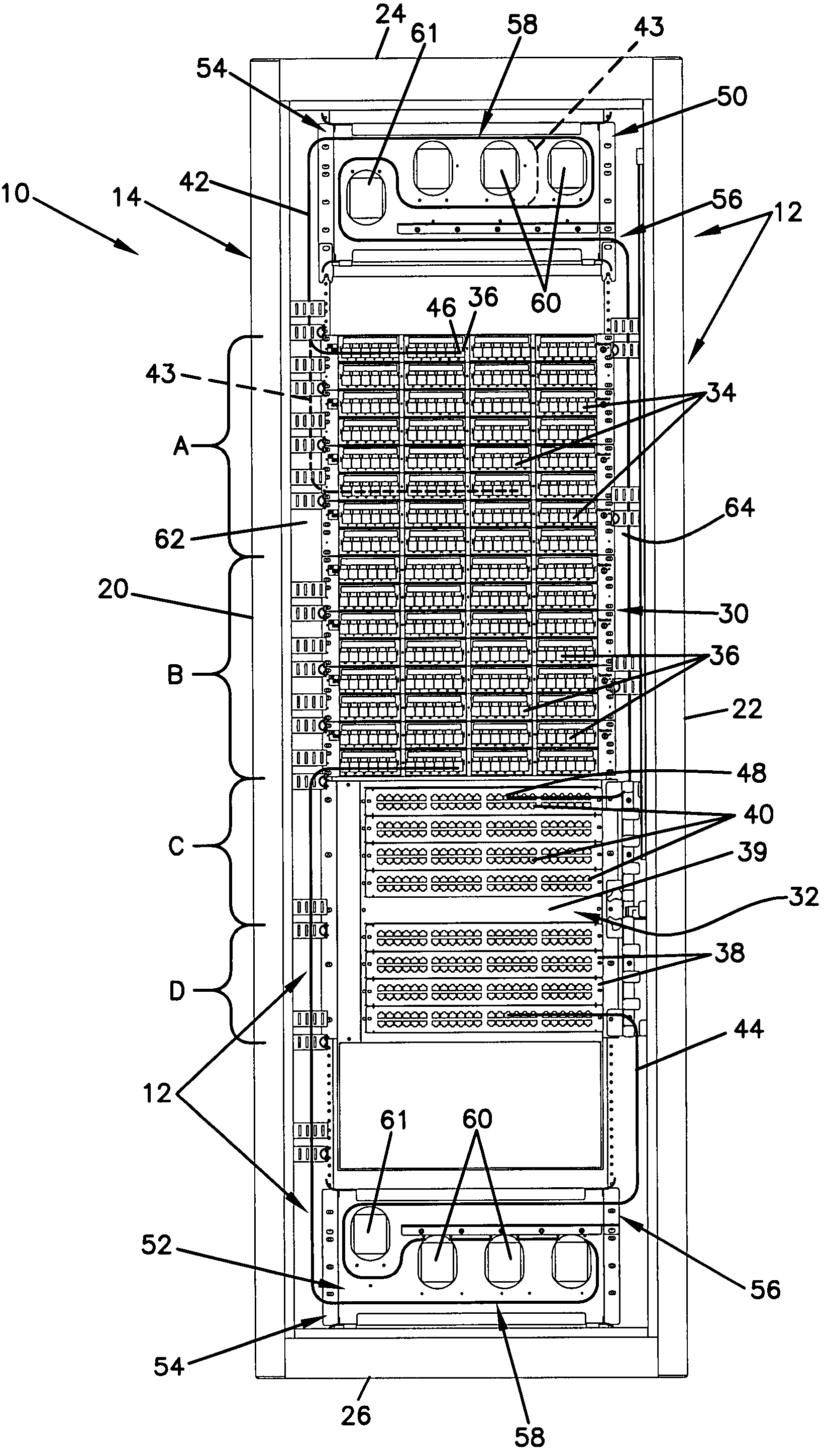
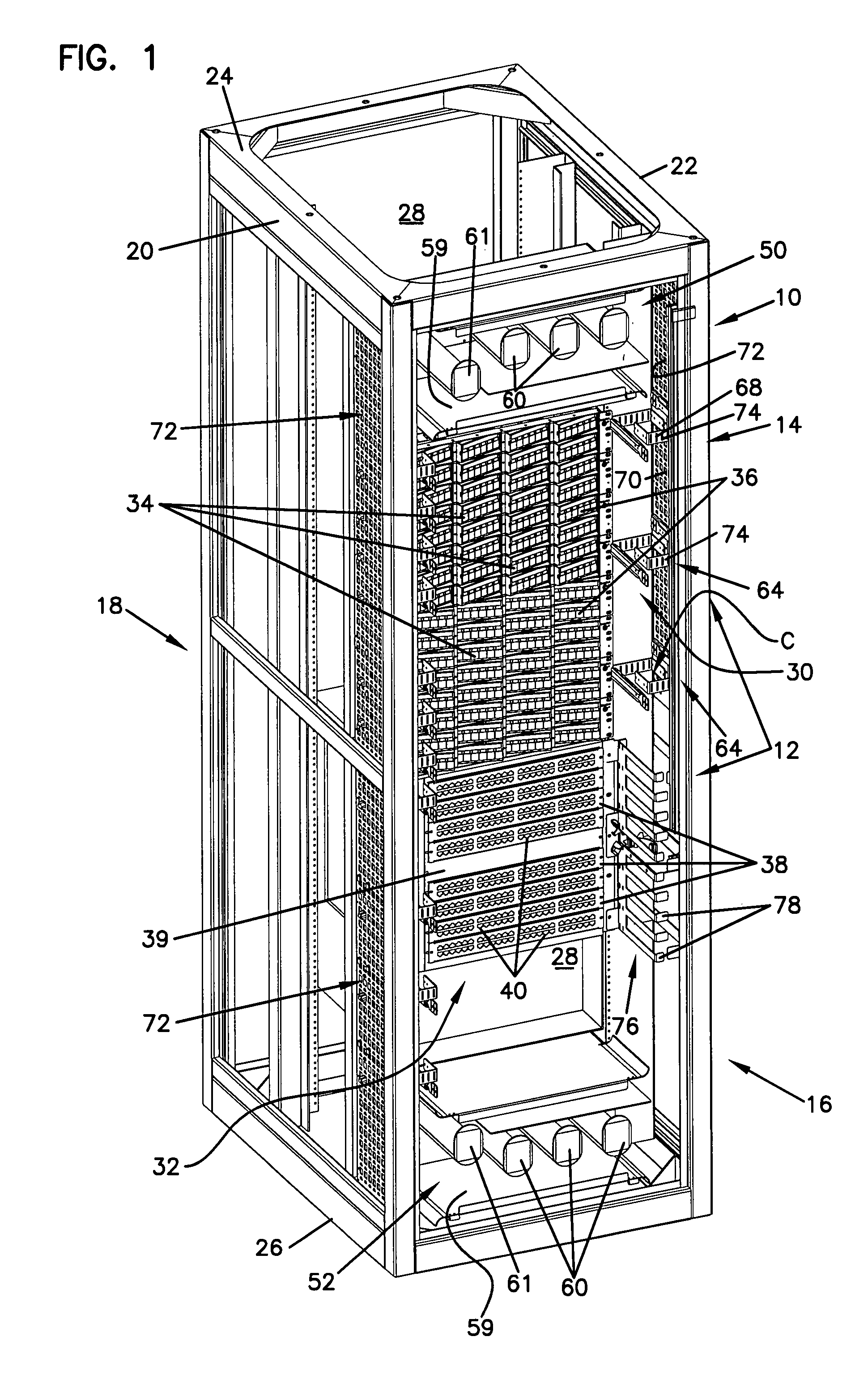
[0023]FIG. 1 illustrates one embodiment of a telecommunications system 10 including a cable management arrangement 12 in accordance with the principles disclosed. In the illustrated embodiment, the cable management arrangement 12 is incorporated into a telecommunications cabinet 14. It is to be understood, however, that the present cable management arrangement 12 can be utilized in systems having other equipment structures, such as racks, wall boxes, and other enclosures or framework.

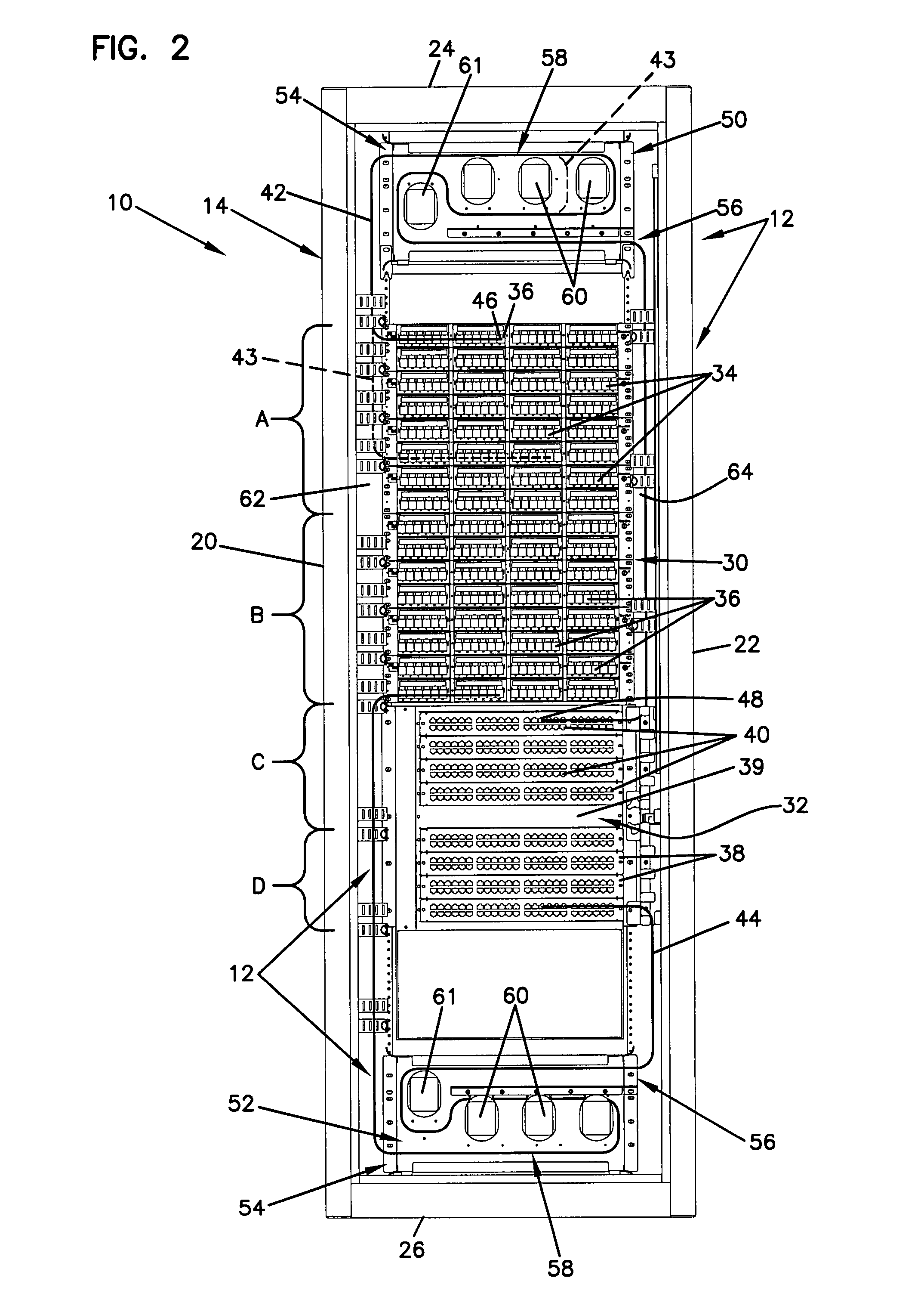
[0024]Referring to FIGS. 1 and 2, the telecommunications cabinet 14 of the present system 10 generally includes a front 16, a rear 18, a first side 20 (e.g., the left side), an opposite second side 22, (e.g., the right side), a top 24, and a bottom ...


PUM


Abstract

A telecommunications system including a frame to which telecommunications equipment is mounted. The frame defines a patch panel region and an active equipment region. Patch cords are interconnected between the patch panel region and the active equipment region. The system further includes a slack storage panel that stores patch cord slack. The slack storage panel defines a single cable routing pathway. The patch cords are routed through the slack storage panel such that no portion of the length of each patch cord overlaps itself. In systems including both copper and fiber cables, the copper cables are routed separately from the fiber cables.

Description

CROSS-REFERENCE TO RELATED APPLICATIONS[0001]This application claims the benefit of U.S. Provisional Application Ser. No. 60 / 959,030, filed Jul. 9, 2007; which application is incorporated herein by reference.FIELD OF THE INVENTION[0002]The present disclosure relates generally to devices for use in the telecommunications industry, and various methods associated with such devices. More particularly, this disclosure relates to a cable routing arrangement and various cable routing constructions for a telecommunications cabinet.BACKGROUND OF THE INVENTION[0003]In telecommunication facilities, telecommunications equipment is mounted to one of a number of framework structures (e.g., cabinets or racks). A vast number of cables are run from, to, and between the equipment mounted to the framework structures. Slack length of each cable is typically routed from the equipment to a side region of the framework structure and wrapped about cable spools for storage. With the vast number of cables, t...

Claims


Application Information

Patent Timeline
Patent Type & Authority Patents(United States)
IPC IPC(8): H02B1/20
CPCH04Q1/064H04Q1/025H04Q1/062H04Q1/066H04Q1/09G02B6/4459H04Q1/13G02B6/44528G02B6/44524G02B6/44526G02B6/4452
Inventor HRUBY, KEVIN L.CORDLE, GLENWALTERS, CINDY S.BARTH, MICHAEL KENNETH
Owner COMMSCOPE TECH LLC
Learn More