Method for generating an annotated network topology

a network topology and network topology technology, applied in the field of methods and systems for generating an annotated network topology, can solve problems such as redundant probes, difficult performance management, and inaccurate estimates of available bandwidth

Inactive Publication Date: 2010-08-24
INT BUSINESS MASCH CORP
View PDF3 Cites 12 Cited by
  • Summary
  • Abstract
  • Description
  • Claims
  • Application Information

AI Technical Summary

Problems solved by technology

However, the distributed and decentralized nature of network resources makes performance management a difficult problem.
However, such methods and systems provide incorrect estimates of available bandwidth when path sharing occurs in the underlying topology.
In addition to inaccuracy, not accounting for sharing may lead to redundant probes when links fail.
However, monitoring traffic can be very intrusive to existing network traffic.
Further, such prior art methods and systems use bottleneck identification tools that could flood the network.
However, such tools can only be used by network operators (e.g., telecommunication companies) and / or on the subparts of the network owned by them.
Thus, such related art methods would require an unrealistic assumption for most networks.
Therefore, there is a need to overcome the above-identified problems as such prior art tools are not viable for production usage.

Method used


Image

  • Method for generating an annotated network topology
  • Method for generating an annotated network topology
  • Method for generating an annotated network topology

Examples


Embodiment Construction

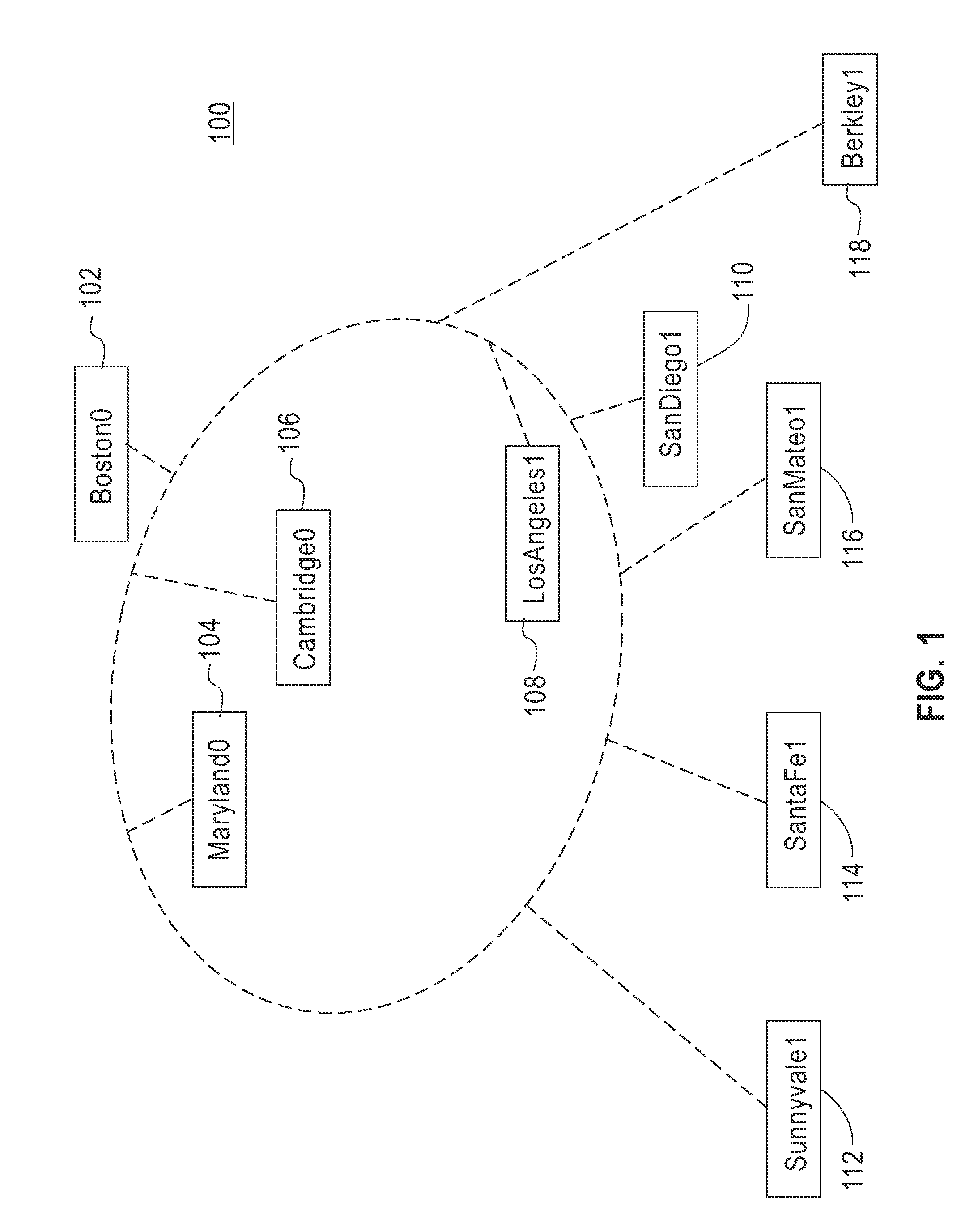
[0025]FIG. 1 illustrates an exemplary high-level network topology 100 to illustrate various aspects of the invention. The network topology 100 discloses a plurality of hub locations representing a set of end points 102, 104, 106, 108, 110, 112 in order to generate a topological map of a network. For example, for ease of illustration, the network topology 100 shows locations of network hubs in cities, states, universities, and so forth. The number of end points shown is merely for purpose of illustration. It will be appreciated that more or less number of end points can be used.

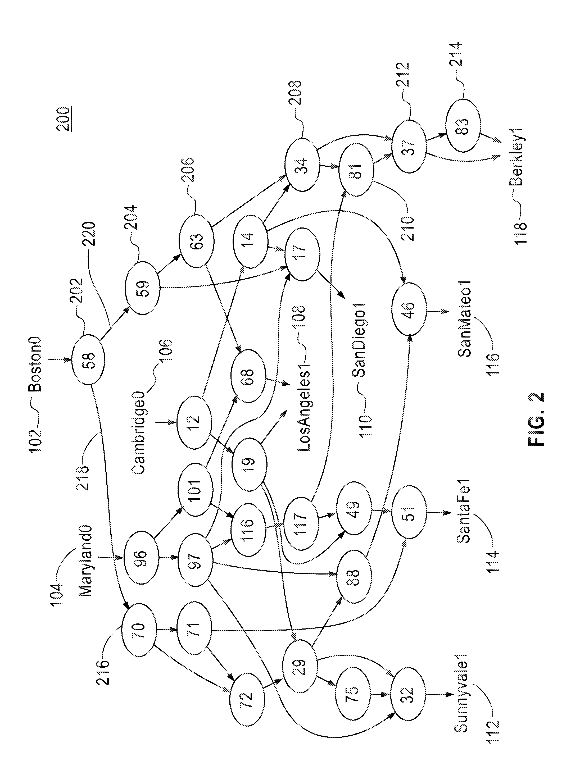
[0026]FIG. 2 depicts an exemplary topological map 200 that can be derived from the network topology 100 as shown in FIG. 1 with given a set of endpoints 102, 104, 106, 108, 110, and 112 (e.g., hub locations in Maryland, Boston, Cambridge, San Diego, etc.). The topological map 200 or a view of the network connecting the endpoints 102-112 can be derived by connecting the endpoints 102-112 as illustrated in FIG. ...


PUM


Abstract

A method of generating an annotated network topology of a network is described. The method includes; deriving a network topology by performing a route tracing utility between each pair of endpoints to determine the route taken by packets; initially annotating each network path with an initial value; determining the available bandwidth of a path connecting a pair of endpoints by performing Transfer Control Protocol (TCP) flows between the pair of endpoints; identifying a bottleneck link in the network path, and annotating all edges to generate an annotated network topology wherein available bandwidth annotation of links inside the network is determined using end-to-end network measurements.

Description

BACKGROUND OF THE INVENTION[0001]1. Field of the Invention[0002]Aspects of the invention generally relate to methods and systems for generating an annotated network topology, and more particularly, for generating an annotated network topology between endpoints of a network using end-to-end measurements.[0003]2. Description of the Related Art[0004]Network performance and availability are determinants of an application's end-to-end performance and user experience. However, the distributed and decentralized nature of network resources makes performance management a difficult problem.[0005]Some prior art methods and systems use latency annotation tools to determine network performance and availability.[0006]Other related art methods and systems use topology-unaware bandwidth annotation tools. However, such methods and systems provide incorrect estimates of available bandwidth when path sharing occurs in the underlying topology. That is, sharing of paths is not taken into account in the ...

Claims


Application Information

Patent Timeline
Patent Type & Authority Patents(United States)
IPC IPC(8): H04L12/28
CPCH04L41/12H04L43/0829H04L43/0852H04L43/0882
Inventor HALEY, MICHAEL R.PRADHAN, PRASHANTSAHA, DEBANJANSAHU, SAMBITSINGH, MANPREET
Owner INT BUSINESS MASCH CORP
Why Eureka
Try Eureka