
Water disk sports game and target

a technology of water disks and sports, applied in the field of games, can solve the problems of requiring a superior swimming technique and process, difficulty in throwing balls with one hand by children and women, and limited gam

Inactive Publication Date: 2010-08-17
MCCARTHY KEVIN
View PDF13 Cites 3 Cited by
  • Summary
  • Abstract
  • Description
  • Claims
  • Application Information

AI Technical Summary

Benefits of technology

[0009]It is an object of the present invention to provide a floating target that can be used with an aquatic disc that is skipped over a body of water.
[0017]To help keep the floating base afloat and upright in the water, additional buoyancy structures may be attached or integrally formed on the circular body.
[0021]In the preferred embodiment, the aquatic disk disclosed in U.S. Pat. No. 6,383,052 is used in the game. Such a disk is made of soft, closed cell foam rubber to reduce injuries caused by impacts. The aquatic disk has a smooth, low coefficient of friction lower surface that enables it to slide easily on the surface of the water while spinning. The aquatic disk has a curved outer perimeter edge with a sharp lower edge which intersects the disk's slightly curved parabolic bottom surface, therefore offering superior hydrodynamic efficiency at the air-water interface. Formed on the perimeter edge of the disk is a raised sidewall. Formed along the inside surface of the raised sidewall is a circular finger groove that enables the disk to be easily grasped and tossed with one hand when wet.
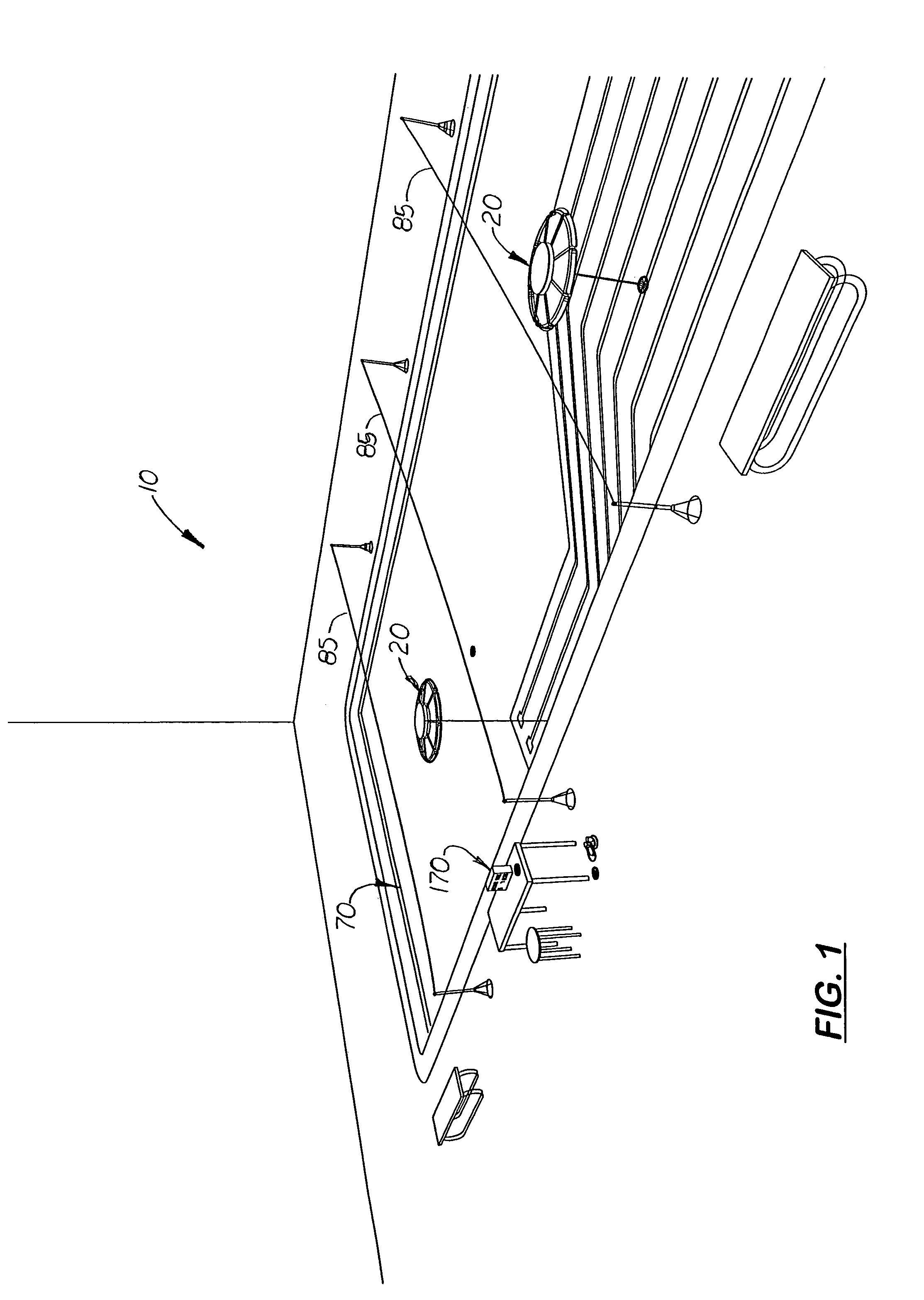
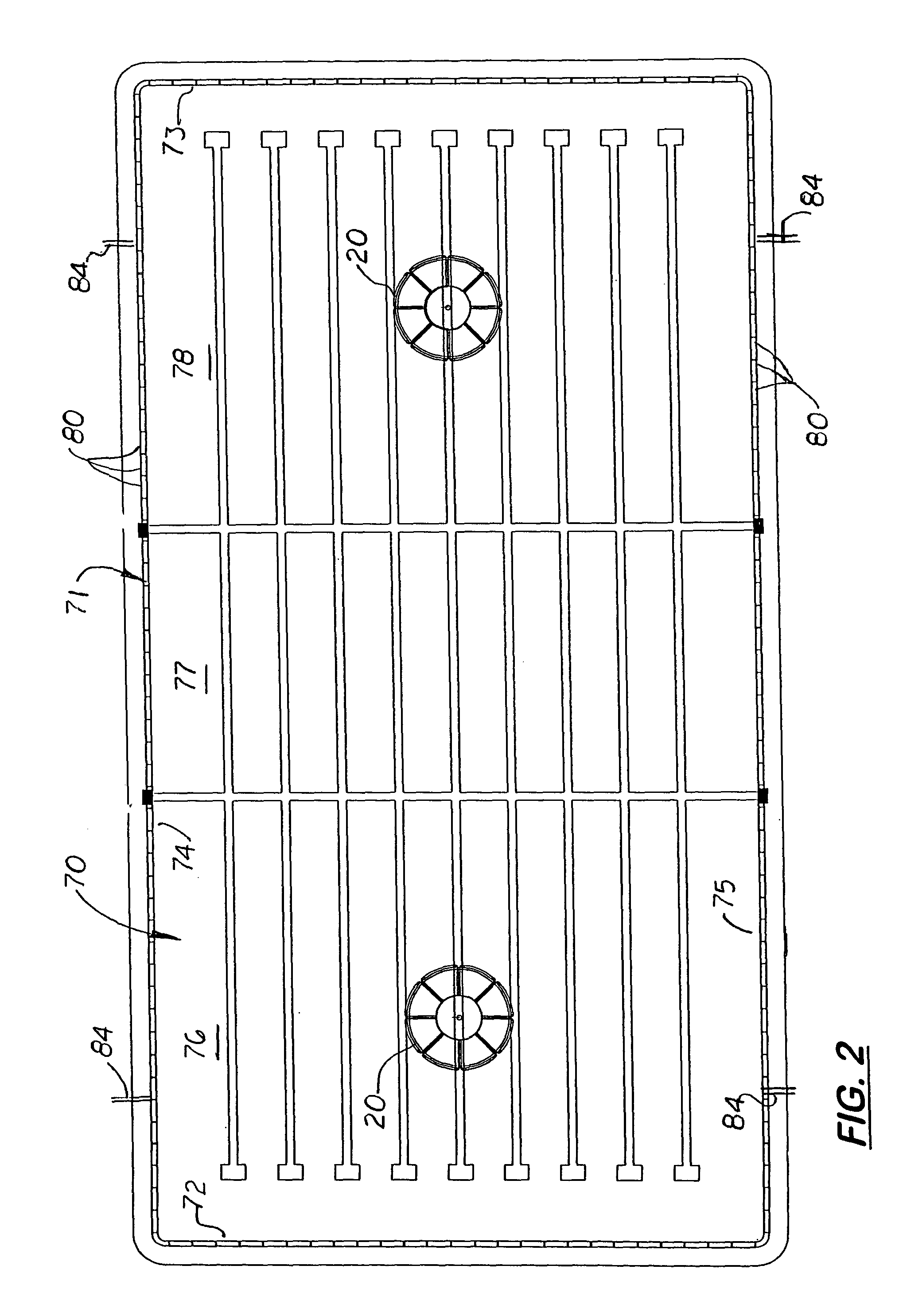
[0022]In the preferred method of playing the game, each player is allowed to wear a pair of special asymmetrical designed fins that provide optimal propulsion. These fins also feature a hoop-shaped perimeter blade which has a soft rounded blade profile with no sharp corners or edges. Players of different positions in the game, and locations of responsibility within the lagoon, may choose to wear specialized swim fins featuring different blade lengths or sizes. Shorter, smaller blades providing quicker pivoting and bursts may be more efficient for positions around the goal. Longer blades, providing higher speeds for distance swimming at the mid-lagoon positions may be desired. During setup, the goals are positioned at opposite end bays of the lagoon and sufficiently away from the back boundary lines and two-sided boundary lines so that each goal must be defended in 360 degrees. A timer and a referee table are setup on one side of the lagoon.

Problems solved by technology

One drawback with water polo is that it requires a superior swimming technique and process, which few people have, and a ball that is difficult for children and women to throw with one hand while treading water or swimming.
Therefore, the game is mostly limited to adult males with particularly strong swimming skills.
Another drawback with water polo is that the game becomes physically confrontational as players fight for the ball that is difficult to grab and pass.

Method used


Image

  • Water disk sports game and target
  • Water disk sports game and target
  • Water disk sports game and target

Examples


first embodiment

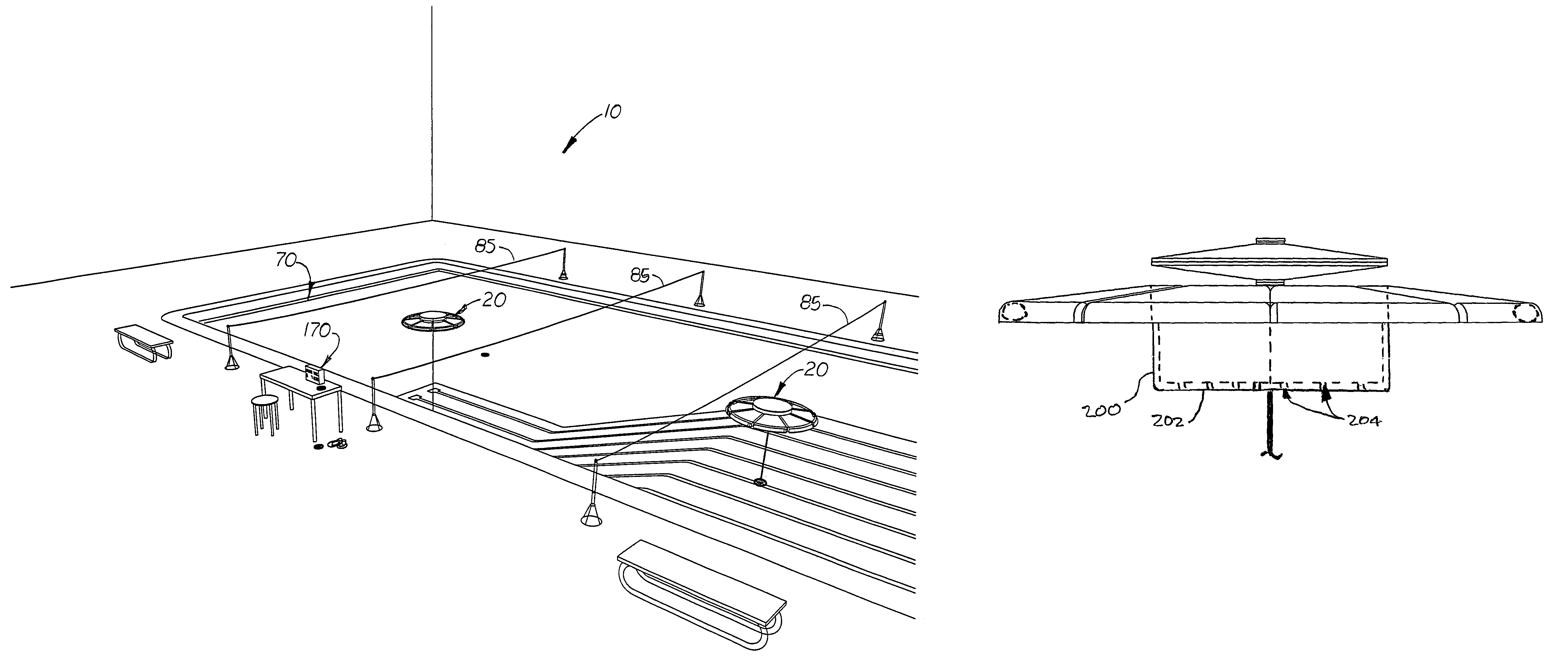
[0051]In the first embodiment, an upper, lid 50 is perpendicularly mounted and attached at an elevated position to the scoring pole 45. The lid 50 is located near the scoring pole's midline axis and includes a lower lid plate 52 and a convex circular upper lid plate 54 connected together along their perimeter edges. The surface of the lower lid plate 52 is designed to guide an aquatic disk 90 thrown into the gap 58 located between the lid plate set 50 and the upper surfaces of the body sections 24A-H shown in FIG. 5. A point may be awarded if the aquatic disk 90 contacts the scoring pole 45 and is retained in the recessed cavity 28. An optional flag pole 58 and flag 60 may be attached to the top end of the scoring pole 45 or to the top of the upper lid plate 54, to improve visibility.

[0052]FIG. 6 is a side elevational view of the floating goal showing an optional cylindrical-shaped barrier 200 that extends through and below the floating base. The barrier 200 is designed to act as a ...

fourth embodiment

[0054]FIGS. 11-13 and 14-16, show a third and fourth embodiment of the floating goal, denoted, 20″ and 20′″, respectively. Both floating goals 20″ and 20′″ replace the floating base 22 with a circular floating rim 110 with radially aligned spokes 112 that connect to a centrally located hub 114. The scoring pole 45 attaches to the hub 114 to hold it in a vertical aligned position above the floating goal 20″ or 20′″. In the floating goal 20″, a lid 50 is attached to the top of the scoring pole 45 and underneath the flag pole 60, so that the aquatic disk 90 must be thrown at a low elevation and angle and contact the scoring pole 45 in order to score. In the floating goal 20′″ the lid 50 is eliminated so that a point is awarded whenever the aquatic disk 90 makes contact with the scoring pole 45.

[0055]FIG. 17 is a side elevational view of the lid 50 integrally formed on the scoring pole which is selectively attached to a modified support post 48. Located around the support post 48 is a p...


PUM


Abstract

A water disk sports game that includes a pair of floating goals located at predetermined distances from each other in a designated boundary area. Each goal includes a vertical scoring pole that extends upward from a large floating base. In a first embodiment, the floating base is a hollow circular floating disk with an upper, diagonally aligned skirt surface that leads to a circular recessed cavity coaxially aligned with the scoring pole. Attached to the scoring pole is an elevated lid which creates a narrow gap between the lid and the top rim of the floating base. In another embodiment, the floating base is a partially submerged rim with radially aligned spokes and a center hub designed to receive the scoring pole. During use, a specially designed aquatic disk is given to one team whose objective is to throw the aquatic disk at the opposing team's scoring pole. If the aquatic disk contacts the scoring pole or is retained in the recessed cavity, a point is awarded to the offensive team or against the defensive team.

Description

[0001]This is a utility patent application which claims benefit of U.S. Provisional Application No. 60 / 993,547, filed on Sep. 12, 2007.BACKGROUND OF THE INVENTION[0002]1. Field of the Invention[0003]This invention pertains to games that use a tangible projectile, and more particularly to such games played in a confined area in a body of water.[0004]2. Description of the Related Art[0005]Water polo is a popular team water sport in which the object of the game is to throw a ball, similar to a soccer ball into a net style goal located at one end of a swimming pool. Each time the ball is thrown into the goal, a point is awarded to the offensive team.[0006]One drawback with water polo is that it requires a superior swimming technique and process, which few people have, and a ball that is difficult for children and women to throw with one hand while treading water or swimming. Therefore, the game is mostly limited to adult males with particularly strong swimming skills. Another drawback w...

Claims


Application Information

Patent Timeline
Patent Type & Authority Patents(United States)
IPC IPC(8): A63B67/00
CPCA63B24/0021A63B65/10A63B67/007A63B67/06A63H33/18A63B63/00A63B2024/0037A63B2067/061A63B2208/03A63B2209/10A63B2225/60A63B2225/605
Inventor MCCARTHY, KEVIN
Owner MCCARTHY KEVIN
Learn More