
Erosion control device and method of use

a technology of erosion control and control device, applied in the field of ground surface covers, can solve the problems of no degree of freedom for vertical or horizontal movement, weakening and ultimate failure of such levees, and tedious installation, and achieve the effect of reducing the extent of erosion of shorelines and levees

Inactive Publication Date: 2010-08-17
KELLEY DENNIS G
View PDF6 Cites 5 Cited by
  • Summary
  • Abstract
  • Description
  • Claims
  • Application Information

AI Technical Summary

Benefits of technology

[0013]Therefore, one object of the present invention is to provide an erosion control device which effectively reduces the extent of erosion of shorelines and levees.
[0015]A further object of the present invention is to provide an erosion control device which is extremely durable and long-lasting.
[0016]Yet another object of the present invention is to provide an erosion control device and method of use which is simple and quick to apply.

Problems solved by technology

In the United States and other countries, miles of shorelines, beaches, and levees are annually subjected to severe erosion which literally washes away earth and exposes higher ground and valuable property to wave action and flooding.
If left unchecked, wave and current action erodes and undermines the foundation of levees, leading to a weakening and ultimate failure of such levees during times of high water or storm surge.
In regard to multi-cast ground surface cover systems, current teachings of interlocking ground surface cover systems are based on individual elements interlocked by rigid or fixed, non-flexible joints between the elements, resulting in no degrees of freedom for vertical or horizontal movement.
This characteristic of multi-cast interlocking element systems presents several significant limitations for application of such systems to erosion control, not the least of which are the tediousness of installation of great numbers of small elements to one another, and the difficulty of removing and replacing individual elements over time.

Method used


Image

  • Erosion control device and method of use
  • Erosion control device and method of use
  • Erosion control device and method of use

Examples


Embodiment Construction

[0023]Before the subject invention is further described, it is to be understood that the invention is not limited to the particular embodiments of the invention described below, as variations of the particular embodiments may be made and still fall within the scope of the appended claims. It is also to be understood that the terminology employed is for the purpose of describing particular embodiments, and is not intended to be limiting. Instead, the scope of the present invention will be established by the appended claims.

[0024]In this specification and the appended claims, the singular forms “a,”“an,” and “the” include plural reference unless the context clearly dictates otherwise. Unless defined otherwise, all technical and scientific terms used herein have the same meaning as commonly understood to one of ordinary skill in the art to which this invention belongs.

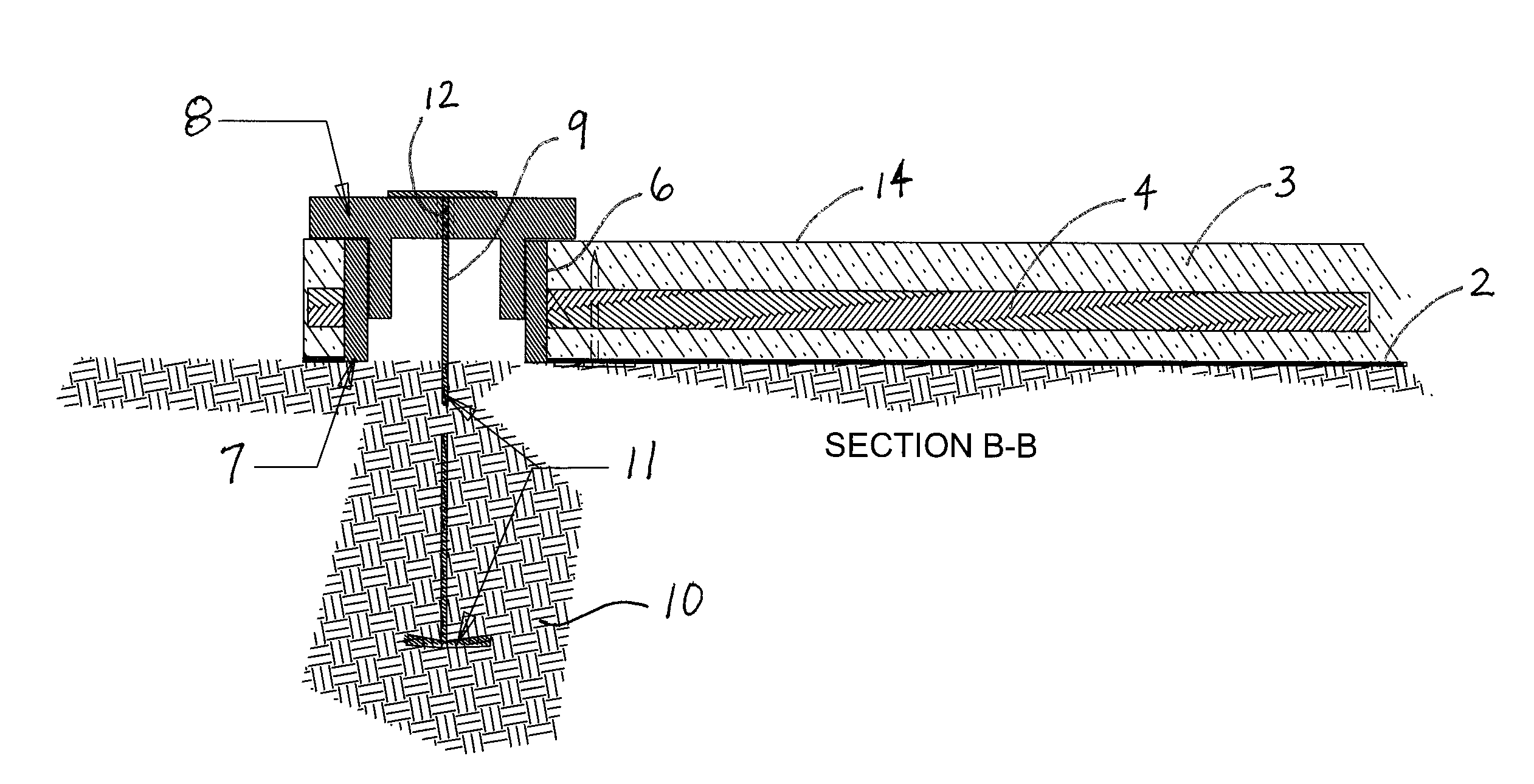
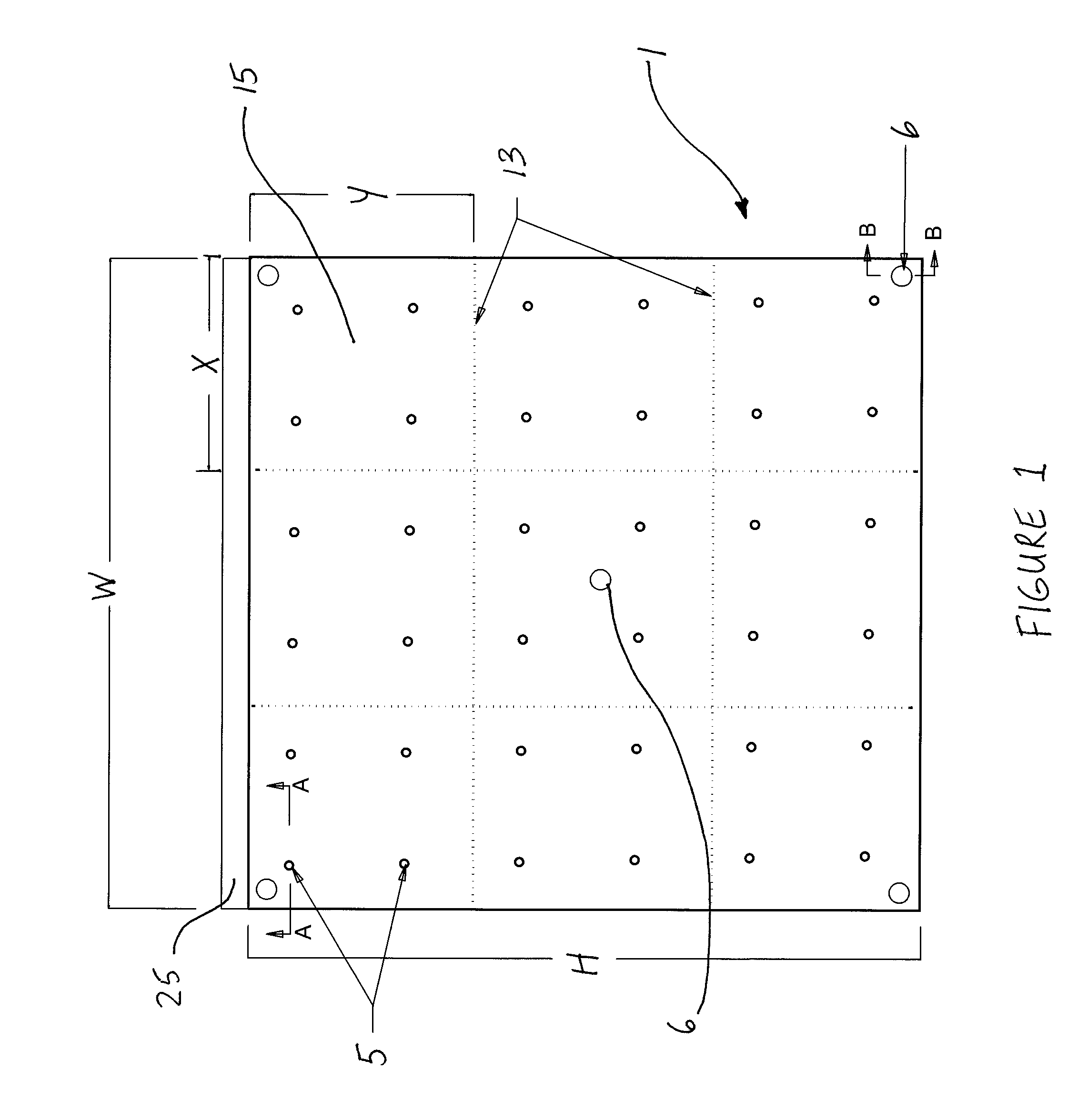
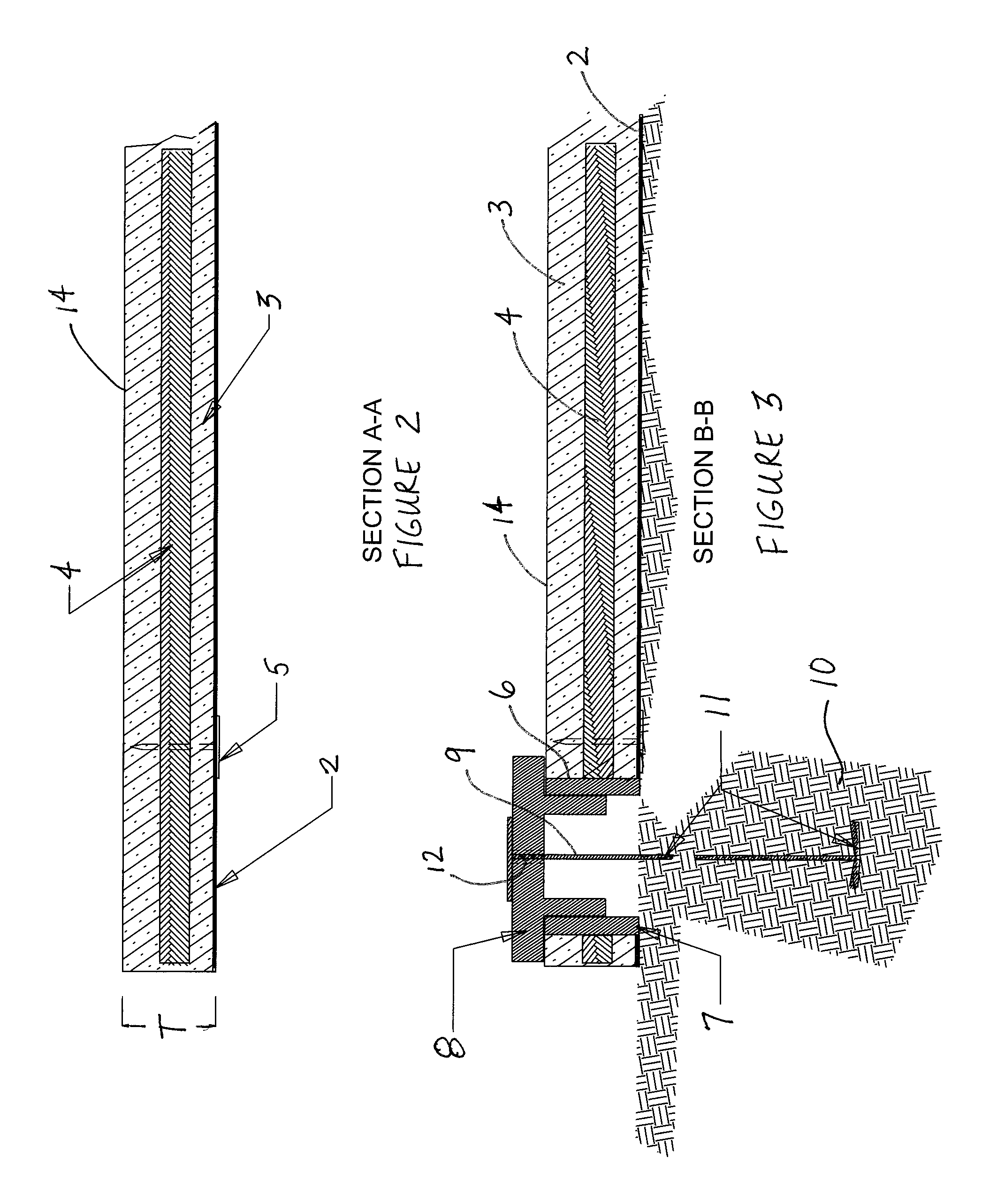
[0025]Turning now to FIGS. 1-3, a preferred embodiment of the invention is shown to comprise a rectangular shaped erosi...


PUM


Abstract

An erosion control device is provided, comprising a panel having a concrete matrix having a top surface and a bottom surface; a turf reinforcement material contained within the concrete matrix; and a geotextile material bonded to the bottom surface of the concrete matrix. The device includes a plurality of shear connectors inserted through the geotextile material, the concrete matrix, and the turf reinforcement material, and at least one flap of geotextile material extending along an edge of the device for overlapping by adjacent panels. The top surface includes score lines adapted to permit the panel to crack and bend along the score lines to adapt to uneven terrain, and also includes installation holes adapted to anchor the device to a levee or shoreline.

Description

CROSS-REFERENCE TO RELATED APPLICATIONS[0001]This Non-Provisional Patent Application, filed under 35 U.S.C. §111(a), claims the benefit under 35 U.S.C. §119(e)(1) of U.S. Provisional Patent Application No. 60 / 814,106, filed under 35 U.S.C. §111(b) on Jun. 14, 2006, and which is hereby incorporated by reference in its entirety.STATEMENT REGARDING FEDERALLY SPONSORED RESEARCH OR DEVELOPMENT[0002]Not applicable.THE NAMES OF THE PARTIES TO A JOINT RESEARCH AGREEMENT[0003]Not applicable.BACKGROUND OF THE INVENTION[0004]1. Field of the Invention[0005]The present invention relates to ground surface covers, including devices and methods employed to reduce the erosion of levees and shorelines from wave action and currents, and more particularly to erosion control devices which are anchored into the soil to form a continuous mat parallel to the shoreline.[0006]2. Description of Related Art[0007]In the United States and other countries, miles of shorelines, beaches, and levees are annually sub...

Claims


Application Information

Patent Timeline
IPC IPC(8): E02D17/20
CPCE02B3/123E02B3/14E02D17/20B28B19/0092B28B23/02
Inventor KELLEY, DENNIS G.
Owner KELLEY DENNIS G
Learn More