
Systems comprising a mechanically actuated magnetic on-off attachment device

a magnetic on-off and mechanical technology, applied in the field of removable attachment devices, can solve the problems of difficult or impossible monitoring with conventional human-based monitoring techniques, the diversity and variability of the structure of the robot platform for shm applications, and the inability to use robotics in shm

Inactive Publication Date: 2010-07-27
UNIVERSITY OF VERMONT
View PDF19 Cites 10 Cited by
  • Summary
  • Abstract
  • Description
  • Claims
  • Application Information

AI Technical Summary

Benefits of technology

The present invention is a magnetic on-off attachment device that can switch between an on state and an off state using a dipole magnet. The device can be used in a mobile apparatus system to attach various components to a chassis. The system includes a plurality of magnetic on-off robotic attachment devices and a controllable articulated linkage that can connect pairs of adjacent attachment devices with each other. The technical effects of this invention include improved attachment and mobility of components in a mobile system, as well as efficient and reliable switching between on and off states.

Problems solved by technology

However, even with all the benefits SHM has to offer, the size, complexity, and accessibility of the structures themselves often makes monitoring difficult or impossible with conventional human-based monitoring techniques.
Perhaps the most significant challenge to creating a robot platform for SHM applications is the diversity and variability of the structures themselves.
Aside from creating small, specialized robots designed to travel across a single structure, or even a single aspect of a structure, utilization of robotics in SHM has been extremely limited.
Numerous specialized robots have been constructed for specific structures; however, these robots are generally limited in mobility and cannot be used on a variety of structure configurations.
RobIn is highly mobile and versatile, but is restricted by limited payload areas and a power cord.
This material can grip non-magnetic surfaces, but disengaging its grip remains problematic.
Also, its use and reuse on rough or scaly surfaces is severely limited.

Method used


Image

  • Systems comprising a mechanically actuated magnetic on-off attachment device
  • Systems comprising a mechanically actuated magnetic on-off attachment device
  • Systems comprising a mechanically actuated magnetic on-off attachment device

Examples


Embodiment Construction

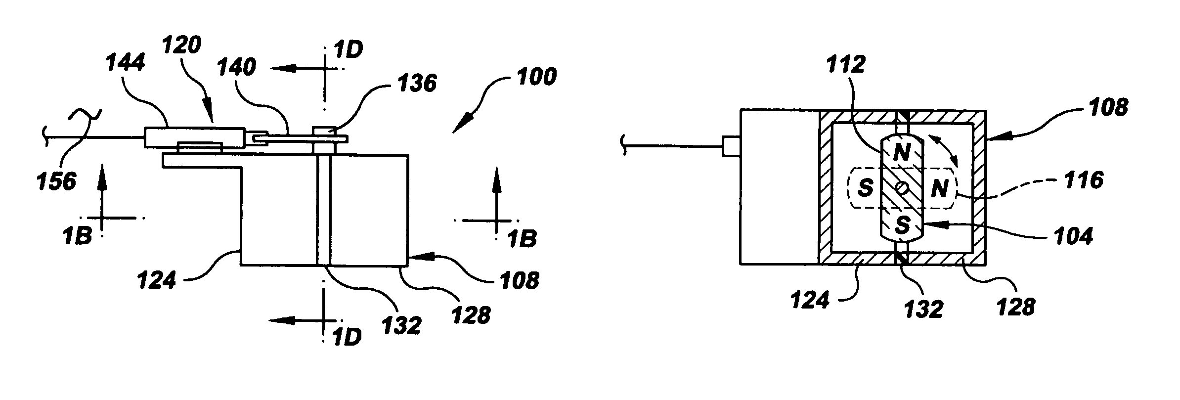
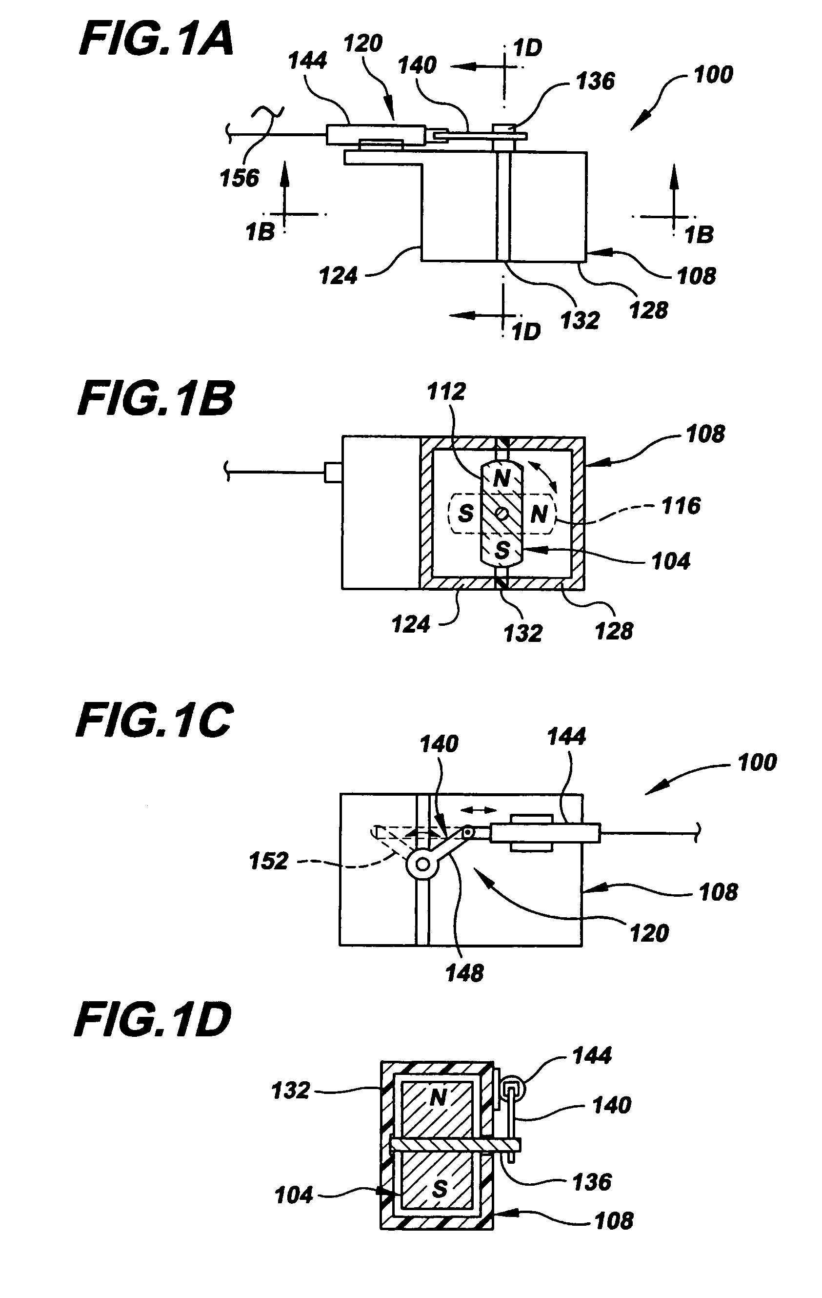
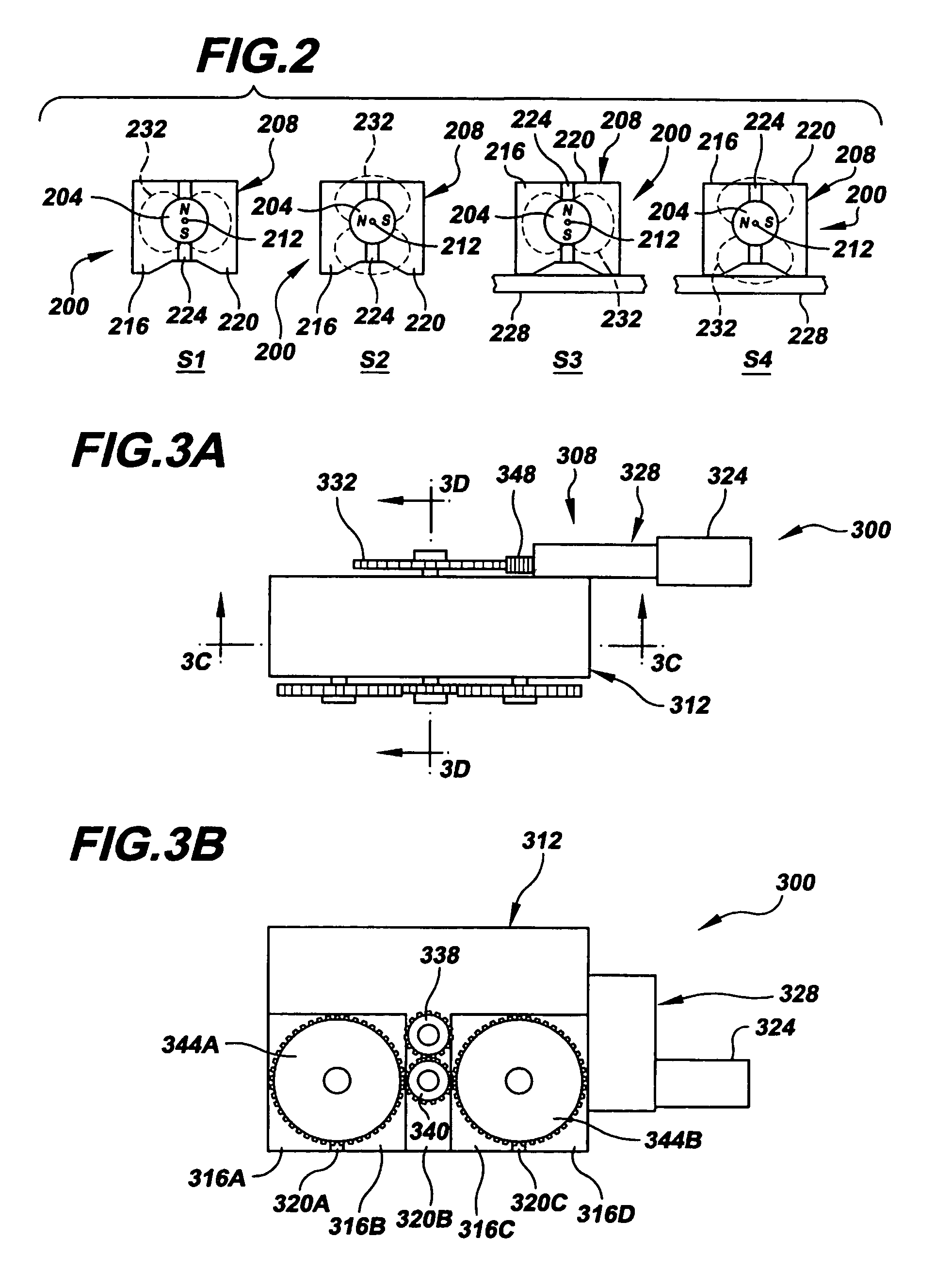
[0027]Referring now to FIGS. 1A-1D, there is shown in accordance with the present invention a mechanical on-off robotic attachment device (MOORAD), which is generally indicated by the numeral 100. As will become readily apparent from reviewing the entire present disclosure, a MOORAD of the present invention, such as MOORAD 100, has numerous applications, some of which are shown and described herein, some of which are mentioned herein and some of which those skilled in the art will recognize after reviewing this disclosure. For example, a MOORAD of the present invention may be used: 1) in connection with mobility systems of mobile apparatuses designed to have mobility on ferromagnetic structures, such as robots, autonomous navigation vehicles, tethered and untethered telemetry controlled vehicles, etc.; 2) as attachment devices for releasably securing items to ferromagnetic structures and 3) in connection with moving ferromagnetic items from one location to another, among others. One...


PUM

PropertyMeasurementUnit
magnetic attractive holding forceaaaaaaaaaa
massaaaaaaaaaa
massaaaaaaaaaa

Abstract

A magnetic on-off robotic attachment device (MOORAD) (100, 300, 400, 624, 624′, 660, 676, 804) is used to make a number of systems, such as a mobile apparatus (608, 644, 668, 700, 700′), a belt mechanism (800) and a sensor device (504, 508, 656). The MOORAD allows the respective system to be removably magnetically attached to a ferromagnetic structure / object (228, 420, 604, 604′, 720A-B, 720A′-B′, 848). Each MOORAD generally includes a dipole magnet (104, 304A-B, 404) movable relative to first and second ferromagnetic portions (112, 116, 316A-D, 408, 412) that are separated by corresponding magnetically insulating portions (120, 320A-C, 416) so as to change that MOORAD between off and on states.

Description

RELATED APPLICATION DATA[0001]This application claims the benefit of priority of U.S. Provisional Patent Application Ser. No. 60 / 553,158, filed Mar. 15, 2004, and titled “On-Off Magnetic Attachment Device,” that is incorporated by reference herein in its entirety.FIELD OF THE INVENTION[0002]The present invention generally relates to the field of removably attachable devices. In particular, the present invention is directed to systems comprising a mechanically actuated magnetic on-off attachment device.BACKGROUND OF THE INVENTION[0003]Structural Health Monitoring (SHM) is vital to ensuring the integrity and longevity of civil structures, as well as providing data and design feedback for the modification or retrofit of existing structures, or the construction of new structures. By observing the performance and state of a structure through SHM techniques, much information can be obtained which quantify how a structure responds to its real world environment and its present state of heal...

Claims


Application Information

Patent Timeline
Patent Type & Authority Patents(United States)
IPC IPC(8): G05B15/00B62D51/06H01H51/30B62D55/265B62D57/024H01F7/04
CPCB62D55/265B62D57/024H01F7/04
Inventor HUSTON, DRYVER R.ESSER, BRIANPLUMPTON, JAMES O.
Owner UNIVERSITY OF VERMONT
Learn More