Motor control apparatus and motor control method
a technology of motor control and motor output, which is applied in the direction of program control, electric programme control, instruments, etc., can solve the problems of affecting the accuracy of torque control, affecting the output of torque, and affecting the torque control of motor factors, so as to suppress the fluctuation of the output of the motor
- Summary
- Abstract
- Description
- Claims
- Application Information
AI Technical Summary
Benefits of technology
Problems solved by technology
Method used
Image
Examples
embodiment 1
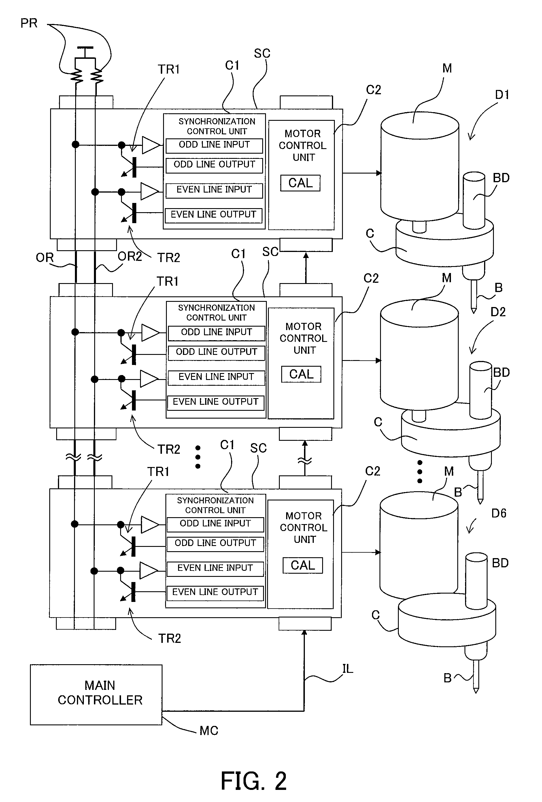
[0053]FIG. 1 illustrates the schematic configuration of a screw tightening system that is Embodiment 1 of the present invention. Reference numeral 1 denotes the entire screw tightening system of this embodiment. Reference numeral 2 denotes a main body of the screw tightening system 1 (hereinafter referred to as an apparatus main body). Reference numeral 3 denotes a lifting mechanism attached to the apparatus main body 2, the lifting mechanism moving a support table 4 up and down.
[0054]Plural (four in FIG. 1) screw tightening drivers (screw tightening apparatuses) D are attached on a horizontal plate 4a of the support table 4. Each of these screw tightening drivers D rotates a screw tightening bit B extending downward from the horizontal plate 4a through a through-hole 4c formed in the horizontal plate 4a. These screw tightening drivers D perform screw tightening operations with respect to a workpiece (an object for screw tightening) (not shown) which is disposed beneath the horizont...
embodiment 2
[0140]FIG. 8 shows a control procedure and operation timings of the screw tightening operations by a screw tightening system that is Embodiment 2 of the present invention. This embodiment shows an example of the case in which five screws are tightened with respect to a workpiece such as the clamp plate 25 or the like by the first to fifth drivers D1 to D5 (hereinafter called the drivers 1 to 5) among all the drivers D1 to D6 described in Embodiment 1. Constituent components in this embodiment identical to those in Embodiment 1 are denoted by the same reference numerals as those in Embodiment 1.
[0141]Embodiment 1 described the case in which the start timings of the seating operations and the torque increase operations of the respective drivers after the synchronization had differences. However, this embodiment will describe a case where the seating operations and the torque increase operations of all the drivers after synchronization are simultaneously started.
[0142]In FIG. 8, (a) to...
embodiment 3
[0176]Embodiments 1 and 2 described the case where the synchronization control for the screw tightening drivers is performed by using the odd and even wired OR lines. However, the same synchronization control can be applied to a motor-driven apparatus other than the screw tightening drivers.
[0177]FIG. 9 illustrates a synchronization control system for performing position control of an object (a robot arm, a positioning table or the like) P in directions of four axes (X-, Y-, Z-, and θ-axes) which is Embodiment 3 of the present invention. Constituent components in this embodiment shown in FIG. 9 identical to those in Embodiment 1 are denoted by the same reference numerals as those in Embodiment 1. In this embodiment, synchronization control of motors MX, MY, MZ, and Mθfor drive in the directions of the X, Y, Z, and θ-axes in place of the screw tightening drivers in Embodiment 1 is performed.
[0178]FIG. 10 shows a control procedure and operation timings of this embodiment. This embodim...
PUM
 Abstract
Description
Claims
Application Information
 - R&D
- Intellectual Property
- Life Sciences
- Materials
- Tech Scout
- Unparalleled Data Quality
- Higher Quality Content
- 60% Fewer Hallucinations
Browse by: Latest US Patents, China's latest patents, Technical Efficacy Thesaurus, Application Domain, Technology Topic, Popular Technical Reports.
© 2025 PatSnap. All rights reserved.Legal|Privacy policy|Modern Slavery Act Transparency Statement|Sitemap|About US| Contact US: help@patsnap.com


