
Weight adjusting structure of golf club head

a golf club head and weight adjustment technology, applied in the field of weight adjusting structure of golf clubs, can solve problems such as odd appearance of the club head

Inactive Publication Date: 2010-07-20
COBRA GOLF
View PDF23 Cites 34 Cited by
  • Summary
  • Abstract
  • Description
  • Claims
  • Application Information

AI Technical Summary

Benefits of technology

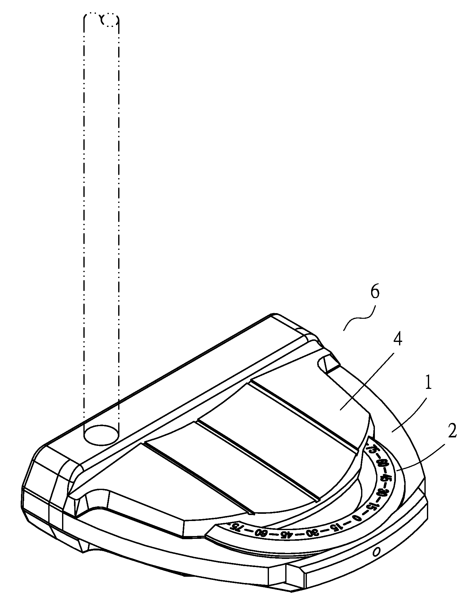
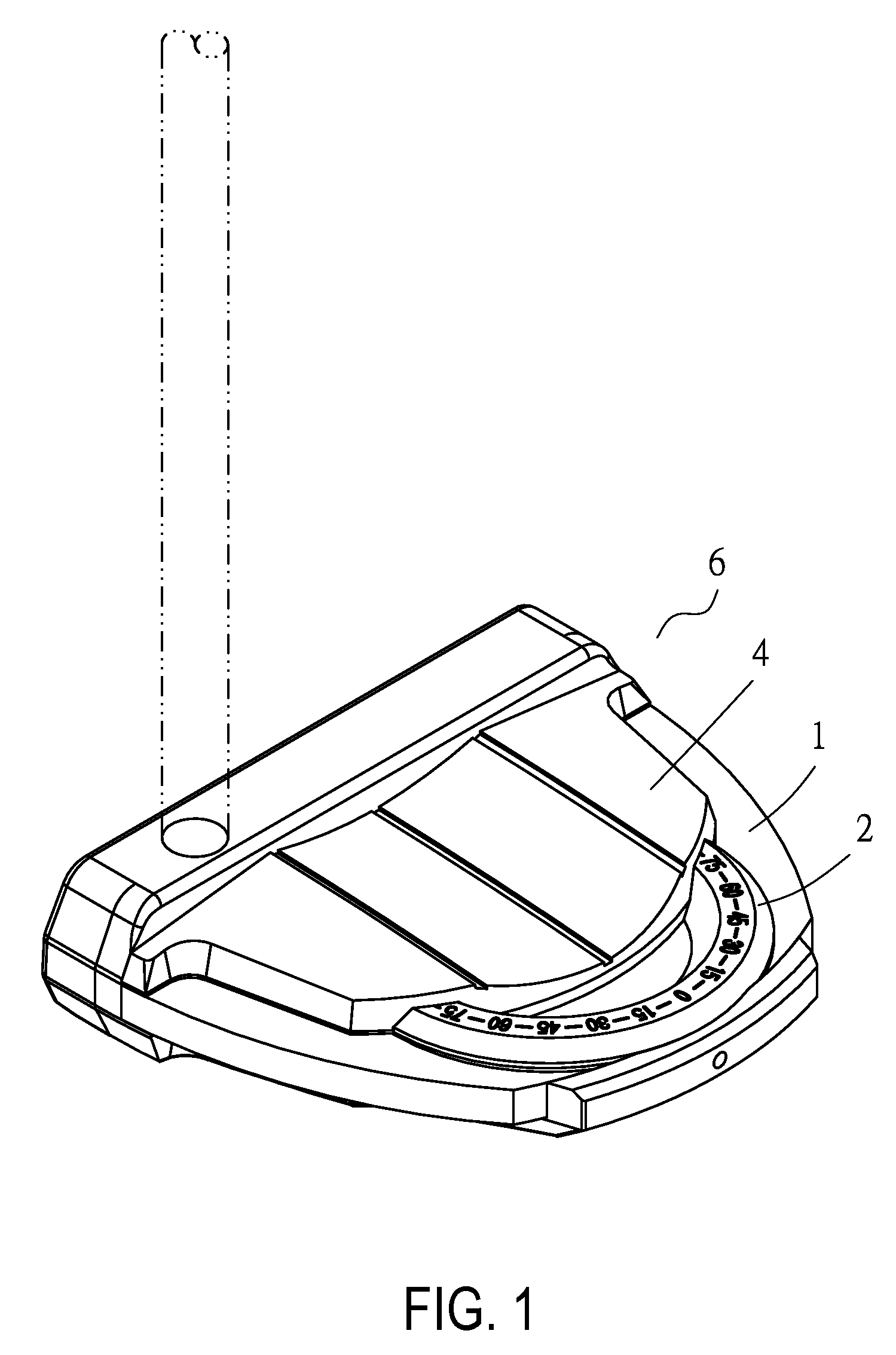
[0005]The present invention is an improvement over the existing weight block assembly installed in a golf club head, with the aims of providing a club head assembly installed in a club head that can be rotated 360 degrees to adjust a weight orientation thereof, so that a location of the gravity center can be set to suit a golfer's swing posture and habits.
[0006]The primary objective of the present invention is to provide a 360-degree rotatable rotary table installed in a body of a golf club head, wherein the rotary table is combined with an incomplete annular weight block at a peripheral portion on an arbitrary side thereof, so that the rotary table and the weight block form a rotary table assembly whose weight orientation can be adjusted. The weighted rotary table assembly installed in the body of the golf club head can be used to adjust a distribution of different weights around 360 degrees, so that a preferred location of the club head's gravity center can be set according to a golfer's swing posture and to a location that the golfer is used to.
[0012]The seventh objective of the present invention is to provide a golf club head having a body which is formed with a cavity on a side thereof for receiving a spring and a ball. Meanwhile, a weighted rotary table assembly installed in the body of the club head has a plurality of notches distributed around a lower periphery thereof. Therefore, the ball which is received in the cavity of the body and constantly pressed upwards can be resiliently engaged with a positionally corresponding one of the notches on the lower periphery of the weighted rotary table assembly to assist in positioning the weighted rotary table assembly.

Problems solved by technology

However, since the weight block is exposed at the lower portion of the club head, the club head presents an odd look.

Method used


Image

  • Weight adjusting structure of golf club head
  • Weight adjusting structure of golf club head
  • Weight adjusting structure of golf club head

Examples


Embodiment Construction

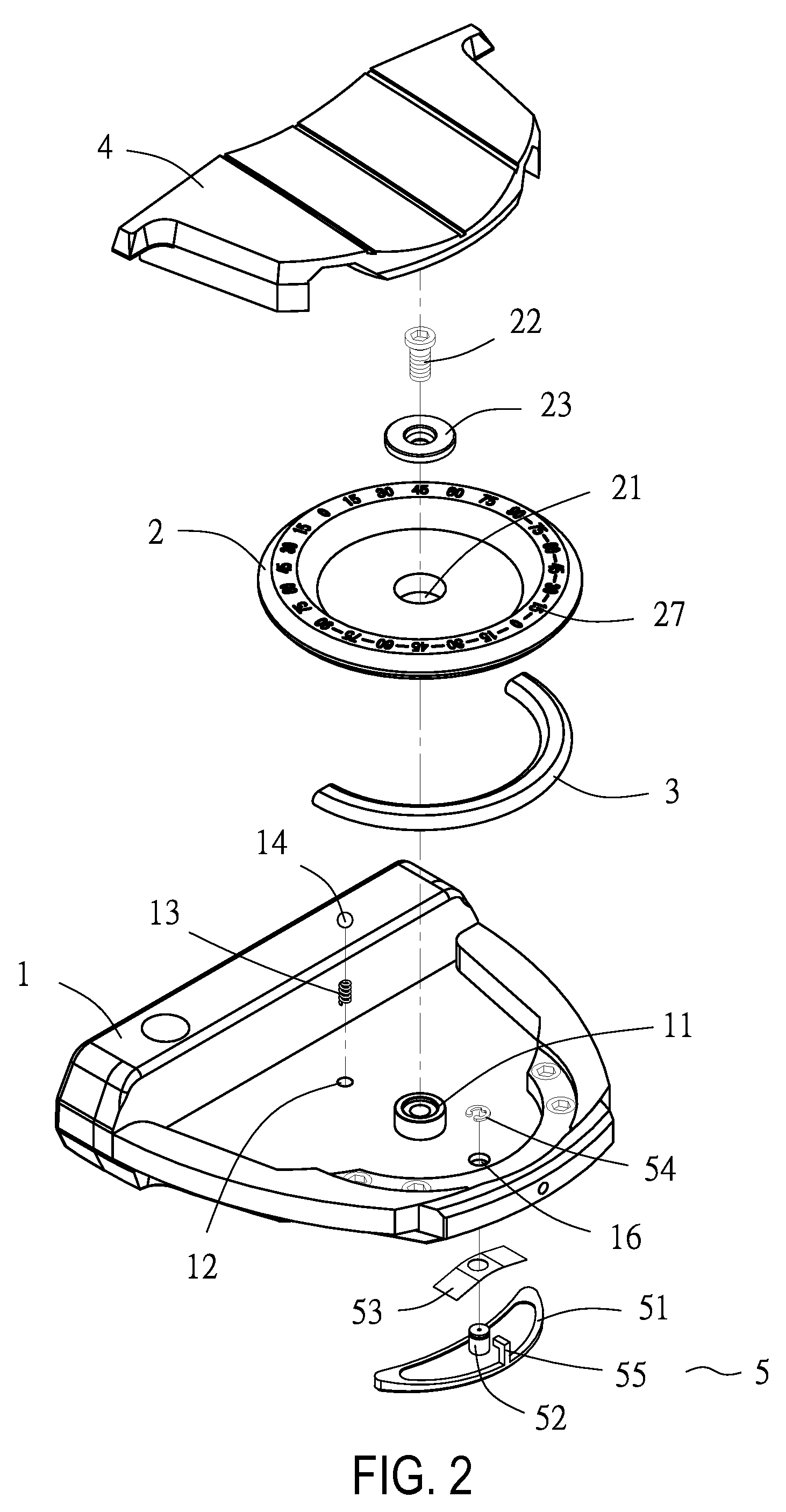
[0023]Referring to FIGS. 2 and 3, a weight adjusting structure of a golf club head according to a first embodiment of present invention comprises a body 1, a rotary table 2 with a weight block 3, an upper body 4, and a locking block assembly 5.

[0024]The body 1 has a supporting tube 11 protruding therefrom and a cavity 12 formed on a side thereof for receiving a spring 13 and a ball 14, as shown in the detailed cross-sectional view taken along Line I-I in FIG. 4A. The body 1 further has a concave portion 15 formed distally on a lower side thereof for receiving the locking block assembly 5.

[0025]The rotary table 2 has a hole 21 in a central portion thereof for receiving a threaded securing element 22 therethrough after the threaded securing element 22 is combined with a bush 23, so that an end of the threaded securing element 22 is screwed into the supporting tube 11 protruding from the body 1, as shown in the detailed cross-sectional view taken along Line I-I in FIG. 4A. In addition,...


PUM


Abstract

A weight adjusting structure of a golf club head comprises a 360-degree rotatable rotary table installed in a body of a golf club head, wherein the rotary table is combined with an incomplete annular weight block at a peripheral portion on an arbitrary side thereof, so that the rotary table and the weight block form a rotary table assembly whose weight orientation can be adjusted. The weighted rotary table assembly installed in the body of the golf club head can be used to adjust a distribution of different weights around 360 degrees, whereby a preferred location of the club head's gravity center can be set according to a golfer's swing posture and a location of the club head's gravity center the golfer is used to.

Description

BACKGROUND OF THE INVENTION[0001]1. Technical Field[0002]The present invention relates to a weight adjusting structure of a golf club head, and more particularly to a weight adjusting structure of a golf club head comprising a club head assembly which is installed in the golf club head and can be rotated 360 degrees for adjusting a weight orientation thereof, so that the gravity center of the club head can be located to suit a golfer's swing posture and habits.[0003]2. Description of Related Art[0004]For a golfer to change the weight orientation of a golf club head to suit his personal swing posture and the location of the gravity center, a weight block has been installed at a lower portion of the club head during the manufacturing process by a golf club manufacturer in an exposed form, so that the weight orientation of the club head can be adjusted with the weight block. The position of the weight block can be shifted to adjust the gravity center of the club head according to the g...

Claims


Application Information

Patent Timeline
Patent Type & Authority Patents(United States)
IPC IPC(8): A63B53/04A63B53/06
CPCA63B53/0487A63B53/06A63B2053/0437A63B2053/0491A63B2053/0416A63B2053/0441A63B60/00A63B53/0416A63B53/0437A63B53/0441
Inventor LIANG, MING-CHINGLIANG, TIEN-KENRICE, SCOTT A.MORRIS, THOMAS C.SORACCO, PETER L.
Owner COBRA GOLF
Learn More