Portable container and dispenser for kegged beer

a technology for kegged beer and dispensers, which is applied in the direction of transportation items, liquid handling, packaging goods, etc., can solve the problems of reducing the volume of beverage one is able to drink, reducing the volume of beverage one, and increasing the cost of canned beverages for consumers

Inactive Publication Date: 2010-07-20
BUHL JR THOMAS R
View PDF14 Cites 40 Cited by
  • Summary
  • Abstract
  • Description
  • Claims
  • Application Information

AI Technical Summary

Benefits of technology

[0020]The bottom section of the outer container may further include a monolithically formed leg portion extending downward and orthogonal from the bottom section of the outer container. Such a leg portion provides support and stability when the container is at rest. The outer container is pivotal about a latitudinal axis such that the leg member is elevated from a ground surface during transportation of the container.

Problems solved by technology

However, the use of canned beverages is more costly to the consumer and creates significant waste in the form of emptied cans.
Further, the use of individual cans reduces the volume of beverage one is able to transport to such remote locations since the can packaging occupies the limited cooler space.
However, this method also has drawbacks.
Further, portable containers are often subject to severe agitation when they are traveling over hilly or rough terrain such as golf courses.
This ruins the taste of the beverage and makes it impossible to pour the beer properly due to excess foaming.
The foam is often waste and is poured off before the beverage is served.
If a carbonated beverage is not handled properly, 50% can be lost to foam waste.
Further, even that portion of the carbonated beverage that does not foam will likely be of poor quality since the loss of carbonation will make the beverage less acidic or “flat”.
However, neither the cooling nor pressurization of the carbonated beverage alone is sufficient to satisfactorily reduce foam.

Method used


Image

  • Portable container and dispenser for kegged beer
  • Portable container and dispenser for kegged beer
  • Portable container and dispenser for kegged beer

Examples


Embodiment Construction

[0032]The present invention will now be described more fully hereinafter with reference to the accompanying drawings, in which a preferred embodiment of the invention is shown. This invention may, however, be embodied in many different forms and should not be construed as limited to the embodiment set forth herein. Rather, this embodiment is provided so that this application will be thorough and complete, and will fully convey the true scope of the invention to those skilled in the art. Like numbers refer to like elements throughout the figures.

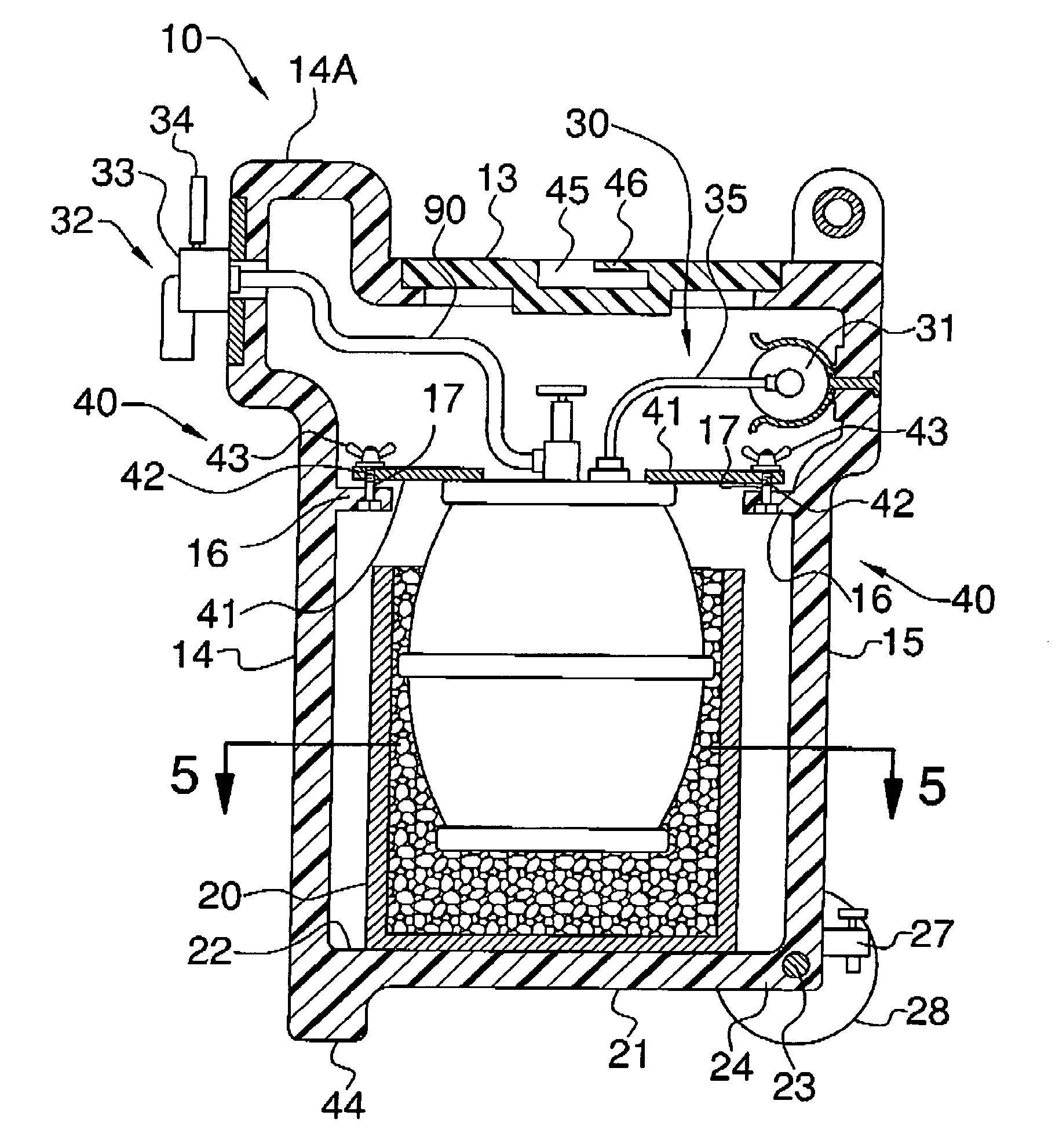
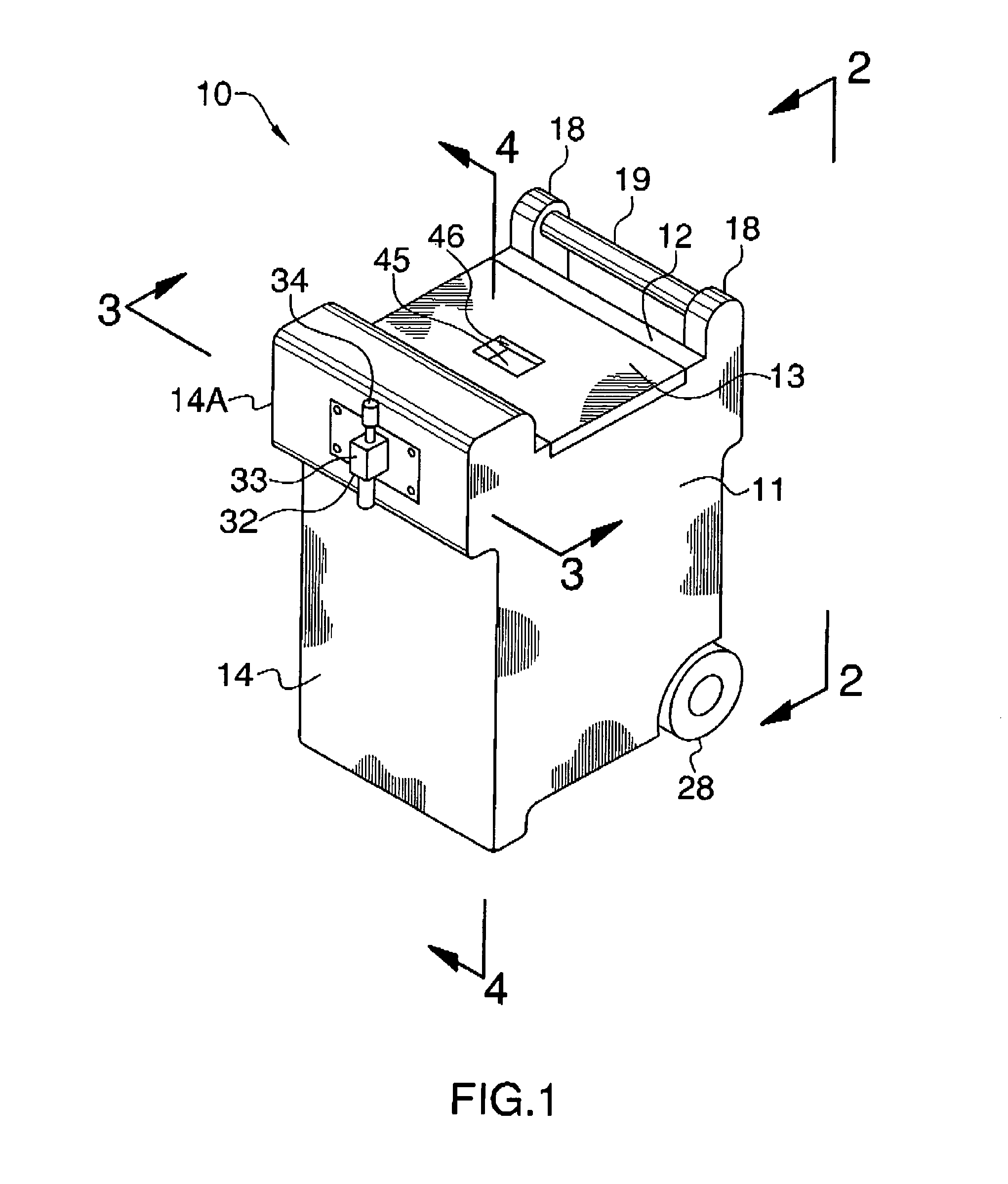
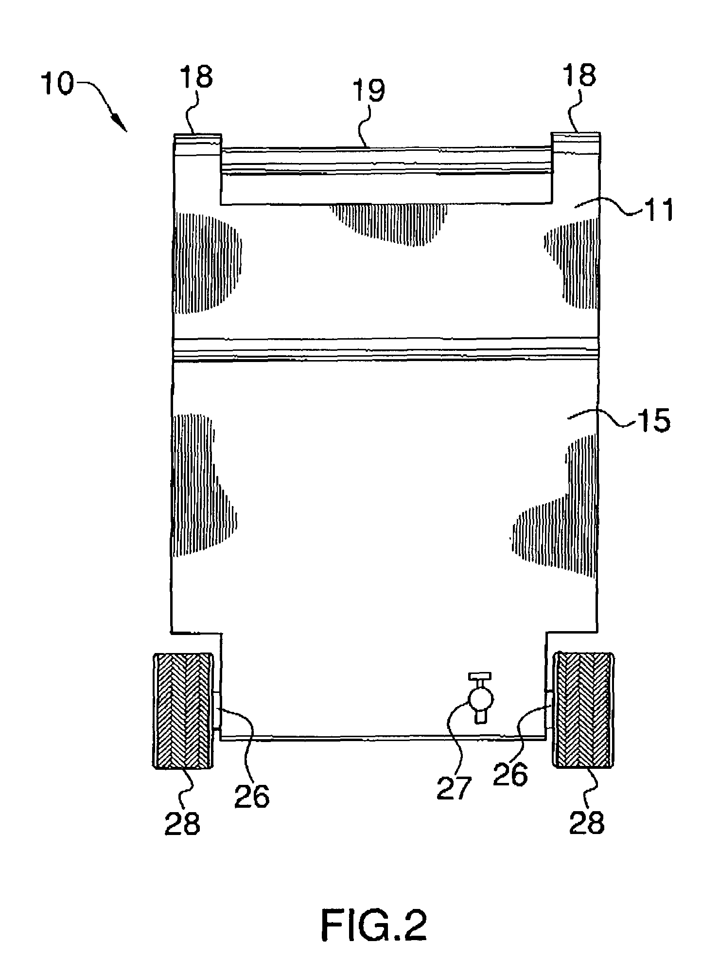
[0033]The apparatus of this invention is referred to generally in FIGS. 1-7 by the reference numeral 10 and is intended to provide a container and dispenser for kegged beer. It should be understood that the container 10 may be used to contain and dispense many different types of fluids.

[0034]Initially referring to FIGS. 1, 2, and 4, the container 10 includes an outer container 11 having a top section 12 provided with an opening centrally form...


PUM

PropertyMeasurementUnit
widthaaaaaaaaaa
volumeaaaaaaaaaa
gas pressureaaaaaaaaaa

Abstract

A combination beer container and dispenser includes an outer container having a top section provided with an opening centrally formed therein. The top section includes a removable lid selectively positional in the opening. The outer container further has front and rear sections and includes a plurality of flange portions extending inwardly and orthogonally from the front and rear sections. An inner container having a cylindrical shape defines a cavity therein. A mechanism for dispensing beer from the keg and a mechanism for securing the keg within the inner container are also included. An axle having opposed end portions is positioned in a bore. A drain cock is directly conjoined to the rear and is manually adaptable between open and closed positions. A plurality of wheels are conjoined to the end portions of the axle. Such wheels include coextensive and juxtaposed ridges for providing traction.

Description

CROSS REFERENCE TO RELATED APPLICATIONS[0001]Not Applicable.STATEMENT REGARDING FEDERALLY SPONSORED RESEARCH OR DEVELOPMENT[0002]Not Applicable.REFERENCE TO A MICROFICHE APPENDIX[0003]Not Applicable.BACKGROUND OF THE INVENTION[0004]1. Technical Field[0005]This invention relates to beverage dispensers and, more particularly, to a portable container and dispenser for kegged beer.[0006]2. Prior Art[0007]The most typical manner to provide cool beverages at remote locations is to transport canned beverages in coolers containing ice and distribute the canned beverages at the remote location. However, the use of canned beverages is more costly to the consumer and creates significant waste in the form of emptied cans. Further, the use of individual cans reduces the volume of beverage one is able to transport to such remote locations since the can packaging occupies the limited cooler space.[0008]To address the problems associated with canned beverages there have been attempts to use kegs or...

Claims


Application Information

Patent Timeline
Patent Type & Authority Patents(United States)
IPC IPC(8): B67D7/80
CPCB67D1/0406B67D1/06B67D1/0857B67D1/0891B67D2001/0098B67D2210/00031B67D2210/00133
Inventor BUHL, JR., THOMAS R.
Owner BUHL JR THOMAS R
Why Eureka
Try Eureka