
Pedestrian vehicle collision safety system

a safety system and pedestrian technology, applied in the direction of pedestrian/occupant safety arrangement, roof, tractors, etc., can solve the problems of increasing the repair cost resulting from low speed impacts, significant injury to pedestrians in the legs, and serious concern about pedestrian impacts, so as to reduce the impact, minimize damage, and mitigate the damage and danger presen

Inactive Publication Date: 2010-07-20
LI PHILLIP S
View PDF7 Cites 33 Cited by
  • Summary
  • Abstract
  • Description
  • Claims
  • Application Information

AI Technical Summary

Benefits of technology

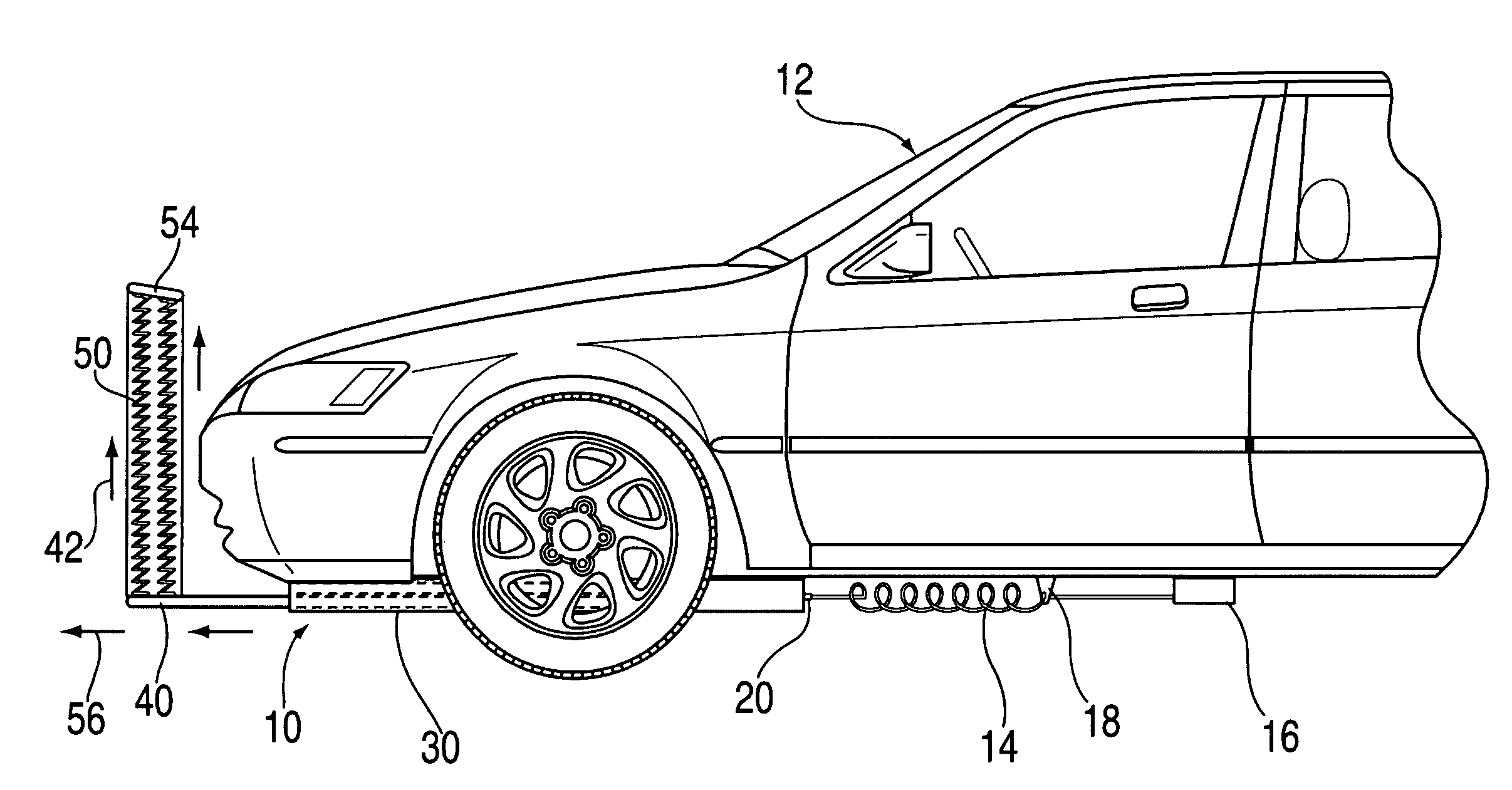
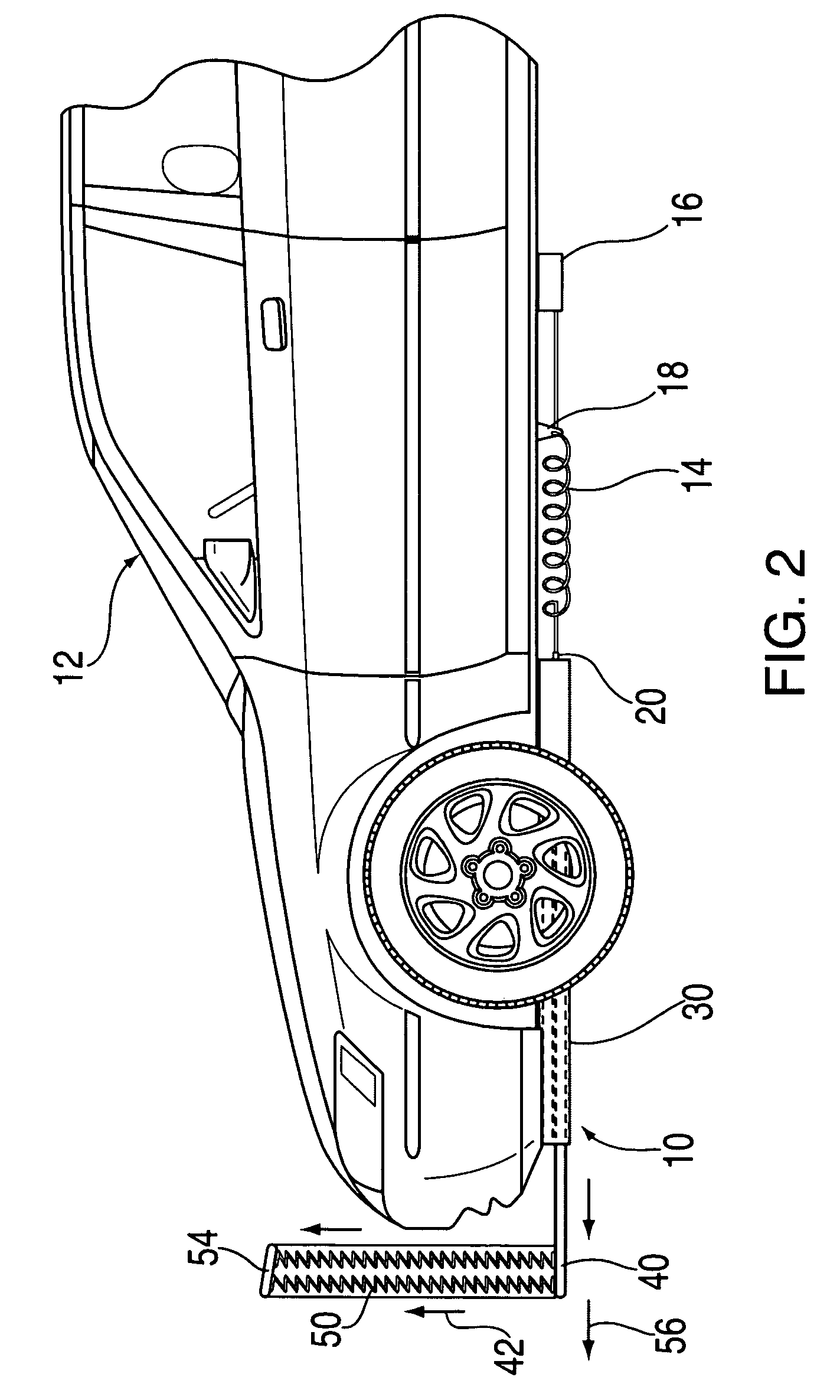
"The present invention is a net-like system that can be quickly deployed in front of a vehicle to catch an unwary pedestrian and reduce the impact force between the vehicle and the pedestrian. The net structure extends horizontally and vertically in front of the vehicle to capture the pedestrian and carry them forward with the vehicle until it can stop. The invention uses collision-sensing equipment to determine when a collision is about to occur and rapidly extends the net-like structure to provide a cushioning structure for the pedestrian. The net structure helps mitigate the damage and danger present by changing the dynamics of the collision."

Problems solved by technology

While previous bumper designs, and those of the present art, have been effective in minimizing damage in vehicle to vehicle collisions or collisions between vehicles and fixed objects, pedestrian impacts have always been a serious concern and have not been well addressed.
In some vehicle collisions with upright pedestrians, bumpers may contact with the pedestrians first through the front bumper of a vehicle, thereby concentrating much of the collision force in a narrow area, usually causing significant injury to the pedestrian in the area of the legs.
Bumpers have also been developed with additional cushion to reduce damaging impact with pedestrians, but one of the problems of such modified bumper design is it tends to increase the repair costs resulting from low speed impacts.
A vehicle structure that is more pedestrian-friendly often conflicts with other customer requirements, such as increased bumper durability, styling and high speed aerodynamics.

Method used


Image

  • Pedestrian vehicle collision safety system
  • Pedestrian vehicle collision safety system
  • Pedestrian vehicle collision safety system

Examples


Embodiment Construction

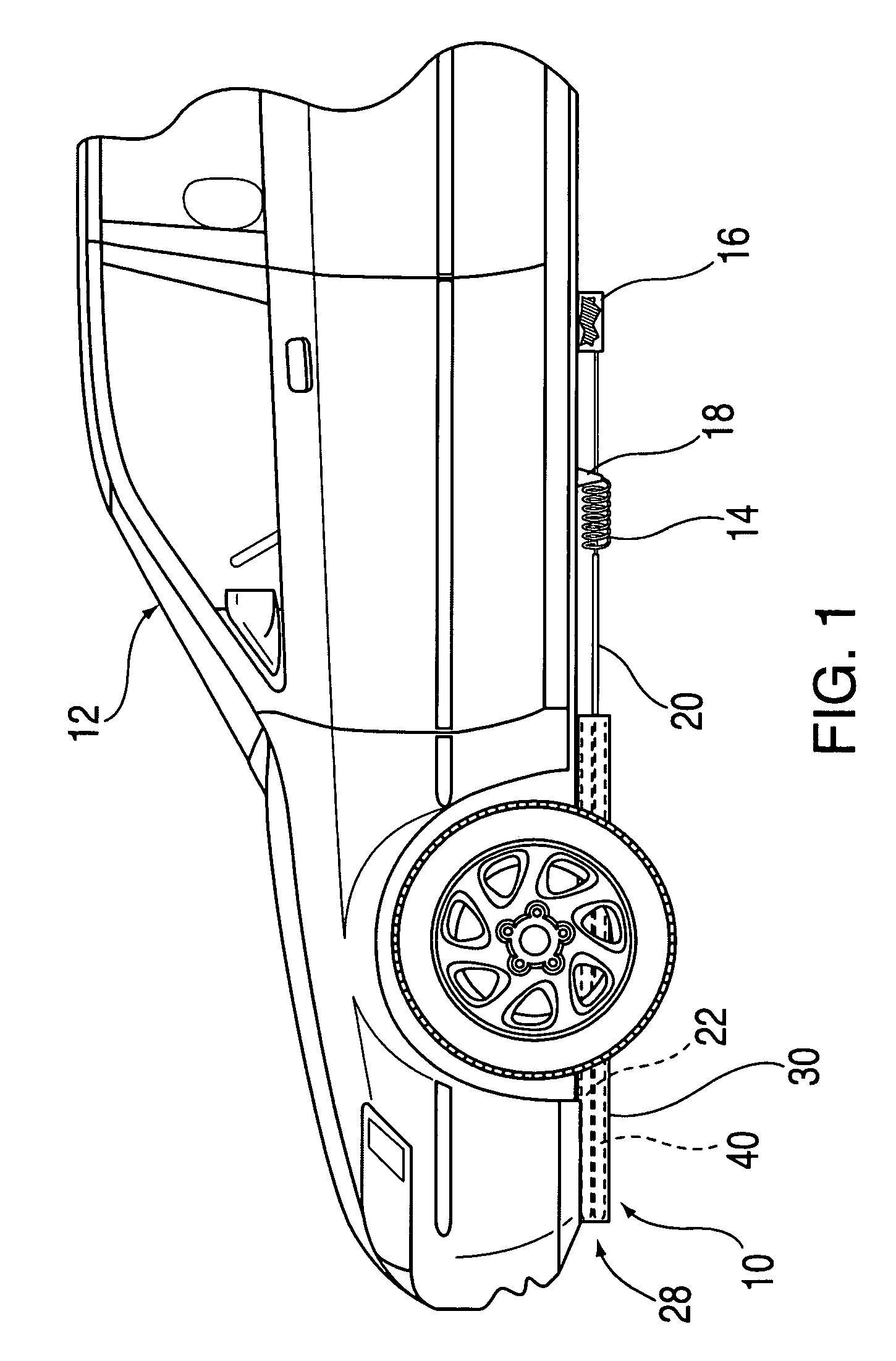
[0018]Now the invention will be described in detail with reference to the various figures wherein like numerals refer to like parts. Turning to FIG. 1, the entire net system 10 is shown fully retracted on vehicle 12 in an un-deployed position. Net system 10 is stowed in system housing 30 underneath the front area of vehicle 12. System 10 is poised under the vehicle to deploy rapidly to provide an expanded net cushion for intercepting an unweary pedestrian who may step in front of a moving vehicle.

[0019]Net system 10 is comprised of deployment controller 16, deployment spring 14, spring anchor 18 and extension rod 20 which is used to propel lower track rail 40 in an outward direction upon deployment. Spring 14 is a spring biased in the retracted position such as to cause a thrust forward in extension rod 20 upon release of deployment controller 16. Deployment controller 16 is controlled by a variety of trigger mechanisms which will be described below. In the retracted position shown ...


PUM


Abstract

An injury mitigation system for a collision between a vehicle and a pedestrian. The invention includes a releasable net-like structure which is deployed from the front of a vehicle to alter the collision dynamics between the vehicle and the pedestrian is disclosed. A release mechanism allows deployment of the net which expands from a small compact size to a large rectangle in a deployed mode, expanding upward by an integrated spring-like structure which then shrouds the front of the vehicle in a short period of time. The system is activated upon sensing an imminent collision at short range in front of the vehicle through use of a motion sensor or other release mechanism.

Description

BACKGROUND OF THE INVENTION[0001]1. Field of the Invention[0002]The present invention relates to a pedestrian safety device, and in particular, a pedestrian safety device deployed from automotive vehicles to mitigate collisions between pedestrians and vehicles.[0003]2. Description of the Related Art[0004]The present invention concerns an extended vehicle bumper-type apparatus that is designed to ride in front of a vehicle to buffer a collision between a vehicle and a pedestrian. Automotive vehicle bumper systems have always been designed primarily to absorb impact forces which may be generated during collisions between the automobile and a fixed structure such as a wall or other object with an unintended collision. Further, bumper systems and other impact absorption devices have been designed over the years to lessen impact forces generated between the collision of vehicles, normally at a slower speed. Such systems have been designed to allow controlled collapse of the bumper so tha...

Claims


Application Information

Patent Timeline
Patent Type & Authority Patents(United States)
IPC IPC(8): B60R21/34
CPCB60R21/34B60R2021/346
Inventor LI, PHILLIP S.
Owner LI PHILLIP S
Learn More