
Fishing lure

a technology of lures and lures, applied in the field of fishing lures, can solve the problems of not being able to adjust the vibration parameters, the vibration of the vibrating member cannot be replaced with different ones, and the lure does not allow the production of any type of lures, so as to achieve the effect of stabilizing the vibration parameters

Inactive Publication Date: 2010-07-20
HERASYMCHUK VASYL VOLODYMYROVYCH
View PDF72 Cites 15 Cited by
  • Summary
  • Abstract
  • Description
  • Claims
  • Application Information

AI Technical Summary

Benefits of technology

[0013]It is another object of the present invention to provide fishing lure, which allows for different combinations, which produces different kind of the lure actions, by having lure that contains numerous skeletons and vibrating bodies, which are interchangeable.
[0024]It is yet another object of the present invention is provide fishing lure which has one of the members comprising at least one springy element between parts of said member and lever areas on a said member, which allows to release an engagement between ball element and socket elements, move said member along retrieval direction and setting up new engagement.

Problems solved by technology

Such lures do not allow producing any types of the fluctuations other than rotational movement of vibrating members.
Also, vibration parameters could not be adjusted and vibrating members could not be replaced with different ones.
Besides, such design does not allow relative move of vibrating member and base part of the lure in retrieval direction upon fish strike.
This reduces reliability of hooking of the fish, because the entire lure needs to be dragged until at least one of the hooks will be set in contact with a fish.
Under such conditions there is a danger of the lure to be relieved by the fish, because there is outside force applied to the lure.
Lure according to U.S. Pat. No. 4,266,360 allows relative move of vibrating member and base part of the lure, but such a move could not be performed in retrieval direction.
The lure can produce planar vibrations, but in working state vibrating member and base part constitute one solid object, so it has all the disadvantages of traditional lures.
Nevertheless, lure action as well as fluctuation parameters are fixed and can not be changed by a fisherman otherwise that by changing retrieval method or speed.

Method used


Image

  • Fishing lure
  • Fishing lure
  • Fishing lure

Examples


first embodiment

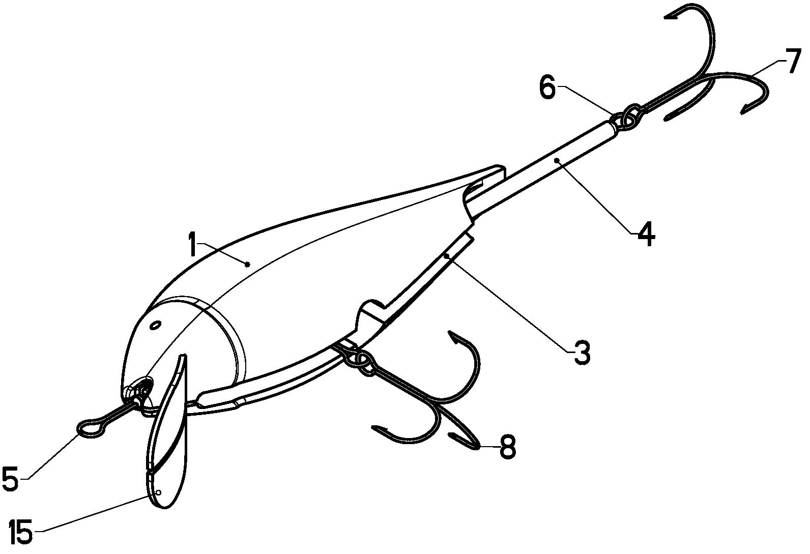
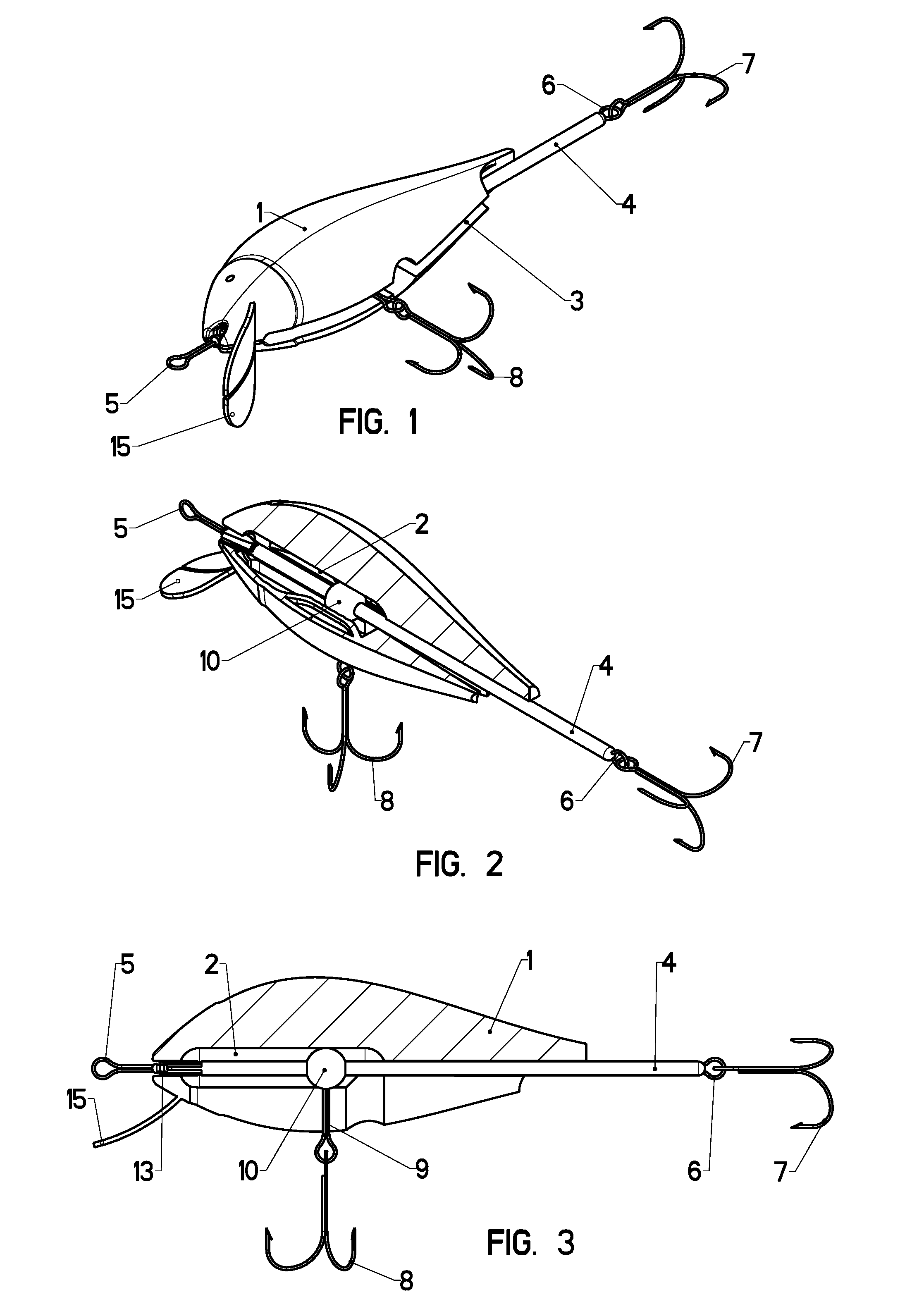
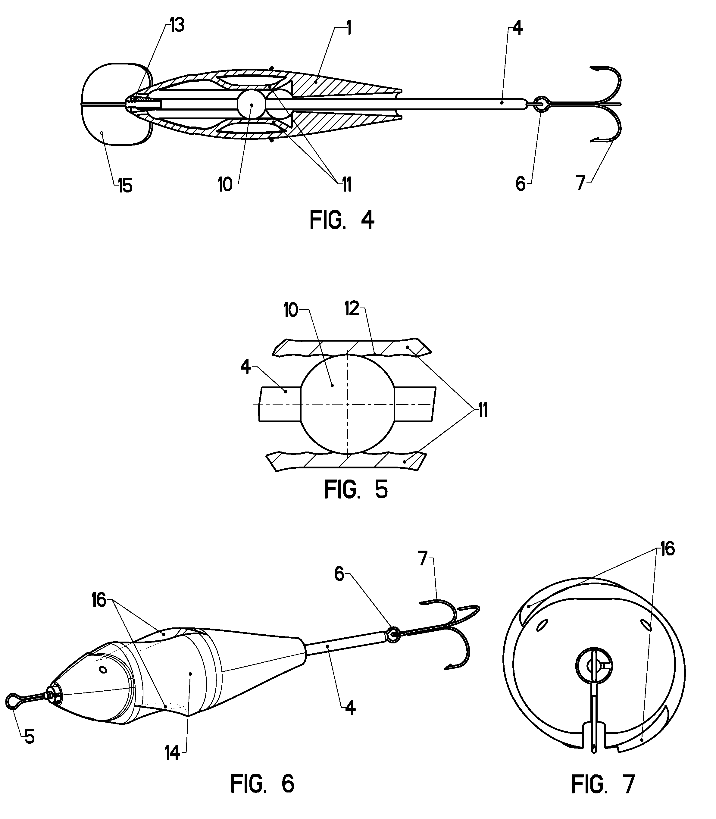
[0059 is represented by a fishing lure having two different vibrating bodies—non-rotating vibrating body 1 and rotating vibrating body 14—each of which could be easily assembled with a skeleton 4, thus forming device capable of producing planar or three dimensional fluctuations when non-rotating vibrating body is used; or fluctuations caused by spinning around an axis, which could be combined with planar or three dimensional fluctuations when rotating vibrating body is used.

[0060]Skeleton 4 has a shape of the axle and non-rotating vibrating body 1 comprises the axle channel 2 for skeleton 4 to move in. Two members—skeleton 4 and vibrating body 1—are assembled by inserting the skeleton 4 through the slot 3 in vibrating body 1. Angular adjustment limiter 13 is attached to the head portion of the skeleton 4. The same head end of the skeleton 4 has an attachment point 5 to a fishing line. Tail 7 and bottom 8 hooks are attached to the skeleton 4 via attachment means 6 and 9. Also, ball e...


PUM


Abstract

The present invention provide a fishing lure with big range of possible wobbling actions due certain amount of degrees of freedom of the joint between two lure's members—skeleton and vibrating body. The amount of degrees of freedom could be changed by fishermen, allowing the vibrating body movement relative to the skeleton and generating wobbling movements by the way of planar or three dimensional vibrating around axes perpendicular to a retrieval direction and / or rotating around an axis which is collinear or parallel to a retrieval direction.

Description

TECHNICAL FIELD OF THE INVENTION[0001]The invention relates to fishing lures used when angling with a fishing rod and a fishing line. Such lures could be used for fishing both salt water and fresh water fish.[0002]More particularly, the invention relates to the fishing lures comprising at least two separate elements, which constitute lure body, and at least one hook attached to it.BACKGROUND OF THE INVENTION[0003]Any fishing lure has two fundamental functions: (1) to attract fish and, ultimately, provoke it to attack the lure and (2) to have such fish reliably affixed to the lure upon such attack, so it could be retrieved from water by a fisherman. Existing lures use following methods to realize first function:[0004]produce mechanical fluctuations of entire lure or a part of one which are transmitted via water environment to the fish receptors;[0005]reproduce general shape, size and color which are typical for a fish prey of a target predatory fish;[0006]use other attraction factors...

Claims


Application Information

Patent Timeline
Patent Type & Authority Patents(United States)
IPC IPC(8): A01K85/00
CPCA01K85/01A01K85/16
Inventor HERASYMCHUK, VASYL VOLODYMYROVYCH
Owner HERASYMCHUK VASYL VOLODYMYROVYCH
Learn More