
Corneal punch

a technology of acorns and punches, applied in the field of corneal punches, can solve the problems of difficult registration of the guide unit with the base unit, and it is possible for a surgeon or technician to have a clear view

Active Publication Date: 2010-07-13
NETWORK MEDICAL PRODS
View PDF11 Cites 3 Cited by
  • Summary
  • Abstract
  • Description
  • Claims
  • Application Information

AI Technical Summary

Problems solved by technology

Firstly, it is difficult to register the guide unit with the base unit because the four pins are difficult to locate within the four holes.
Secondly, because the guide unit is substantially solid and opaque, it is not possible for a surgeon or technician to have a clear view of the donor cornea when cutting the donor graft therefrom with a corneal trephine.

Method used


Image

  • Corneal punch
  • Corneal punch
  • Corneal punch

Examples


Embodiment Construction

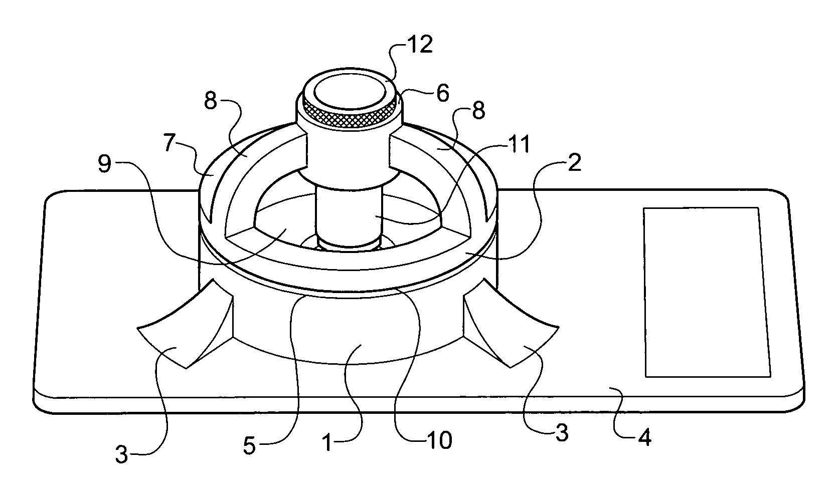
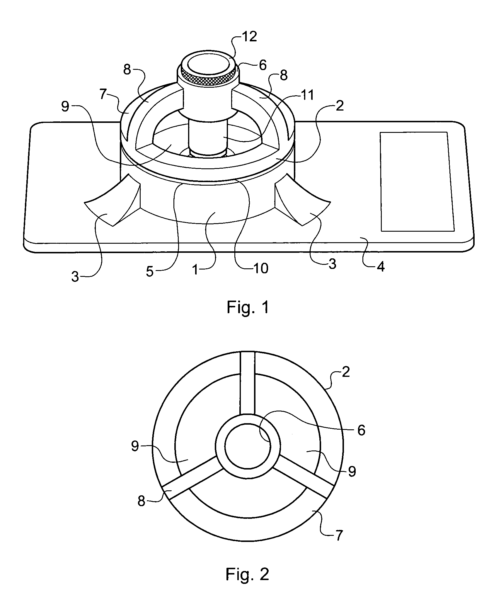
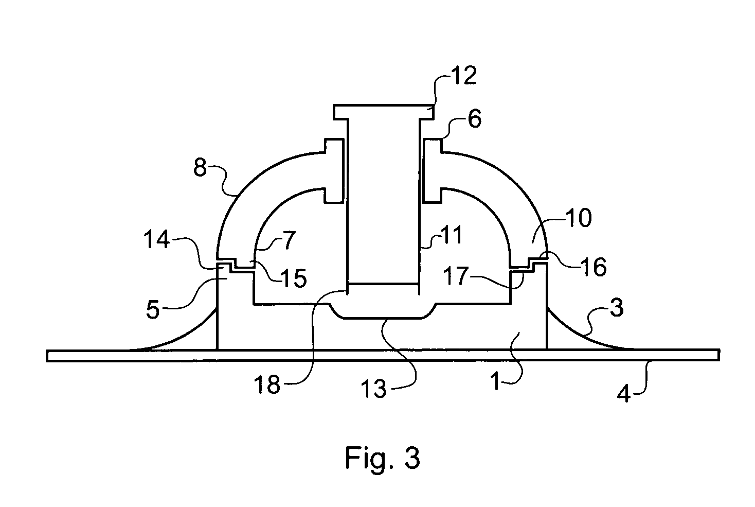
[0028]FIG. 1 shows a corneal punch comprising a base unit 1 and a guide unit 2 located in registration therewith. The base unit 1 includes peripheral finger grips 3 and is mounted on a plate 4 so as to allow it to be held steady on a flat surface. The base unit 1 is generally cylindrical in shape, and includes an internal central well 13 (see FIG. 3) which is in the form of a generally circular concave dish adapted to support a donor cornea. An annular mating surface 5 is provided at the top of the base unit 1, the well 13 being coaxial with the annular mating surface 5. The guide unit 2 has an inner annular guide shaft 6 connected to an outer locating ring 7 by way of three spokes 8, with windows 9 being defined between the spokes 8. The outer locating ring 7 is provided with a mating surface 10 at its base, the mating surface 10 being shaped so as to co-operate with the mating surface 5 of the base unit 1 and to hold both the base unit 1 and the guide unit 2 in registration with e...


PUM


Abstract

A corneal punch comprising a base unit having a first annular mating surface surrounding a well in which a donor cornea may be located, and a separate guide unit including an inner annular guide shaft and an outer locating ring connected to the guide shaft and having a second annular mating surface. The base unit and the guide unit may be releasably positioned in registration with each other by way of the first and second mating surfaces such that the guide shaft is substantially coaxial with the well.

Description

CROSS-REFERENCE TO RELATED APPLICATIONS[0001]This application claims priority of my U.S. Provisional patent Application No. 60 / 298,717, filed 15 Jun. 2001, and incorporated herein by reference.STATEMENT REGARDING FEDERALLY SPONSORED RESEARCH OR DEVELOPMENT[0002]Not applicableREFERENCE TO A “MICROFICHE APPENDIX”[0003]Not applicableBACKGROUND OF THE INVENTION[0004]1. Field of the Invention[0005]The present invention relates to a corneal punch for cutting corneal grafts from donor corneas prior to transplantation of the grafts to patients with damaged or diseased corneas.[0006]2. General Background of the Invention[0007]In the field of eye surgery, it is sometimes necessary to perform a corneal transplant by replacing a diseased or damaged cornea of a patient with a donor cornea harvested from an immunologically compatible cadaver. This is generally achieved by removing at least a central portion of the diseased or damaged cornea from a patient's eye using a trephine, using a corneal p...

Claims


Application Information

Patent Timeline
Patent Type & Authority Patents(United States)
IPC IPC(8): A61F9/00A61F9/01A61F9/011A61F9/013
CPCA61F9/0133
Inventor WESTON, PHILIP DOUGLAS
Owner NETWORK MEDICAL PRODS
Learn More