
Bi-directional bone length adjustment system

a technology of bone length adjustment and bi-directional motion, which is applied in the field of bone length adjustment system, can solve the problems of adverse bone length increase, unidirectional motion, and lack of control

Inactive Publication Date: 2010-07-13
EKSLER AUGUST +2
View PDF25 Cites 158 Cited by
  • Summary
  • Abstract
  • Description
  • Claims
  • Application Information

AI Technical Summary

Benefits of technology

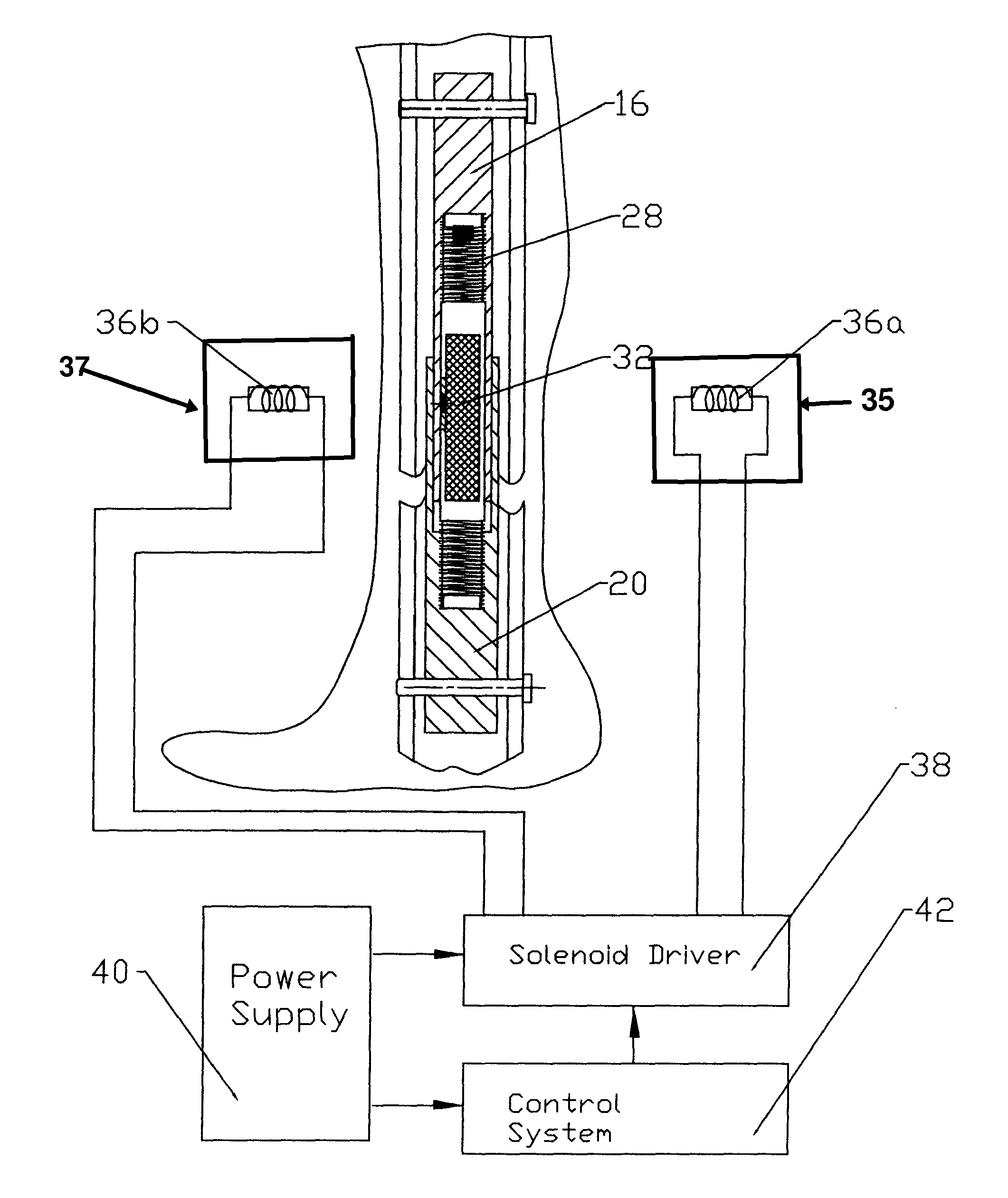
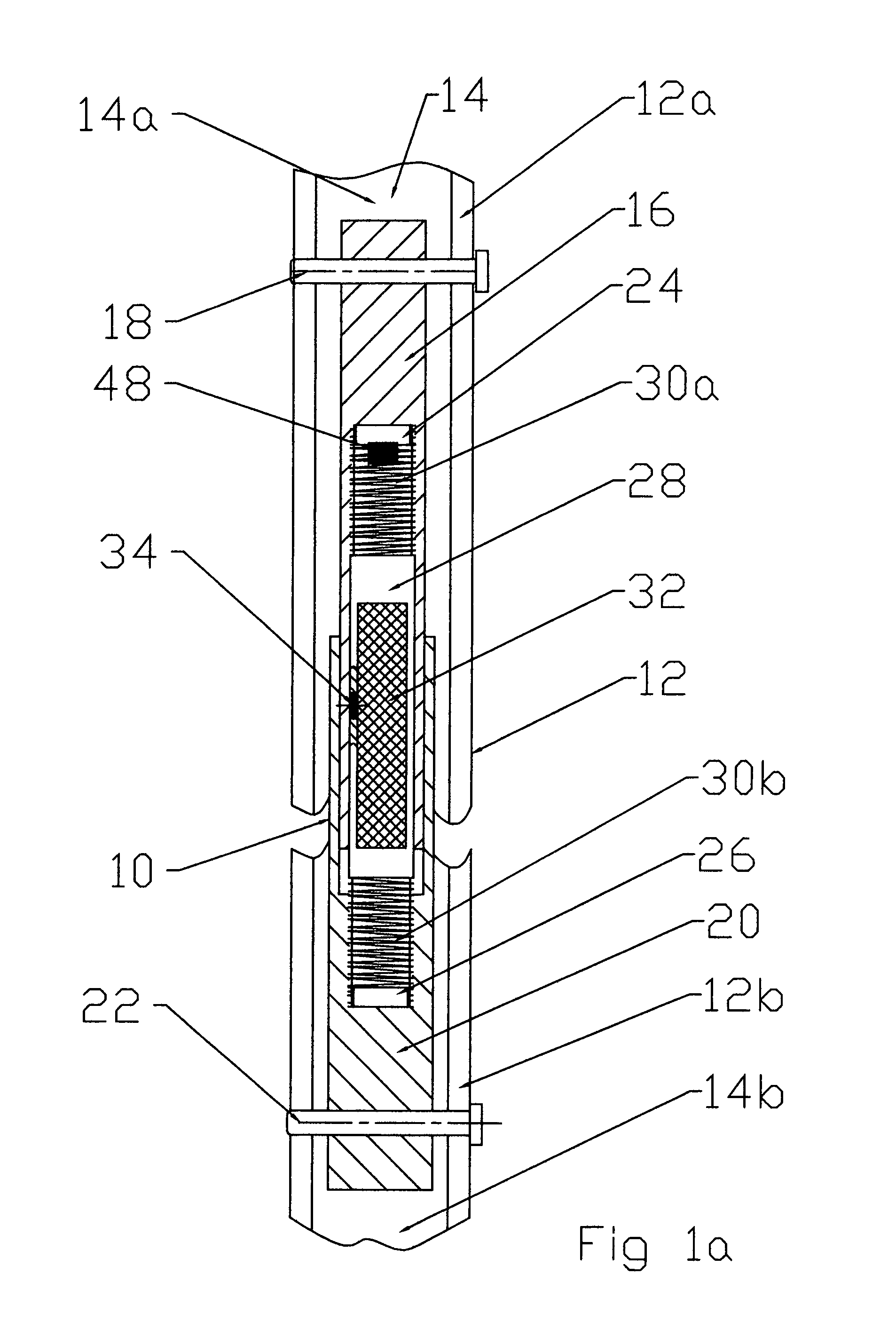
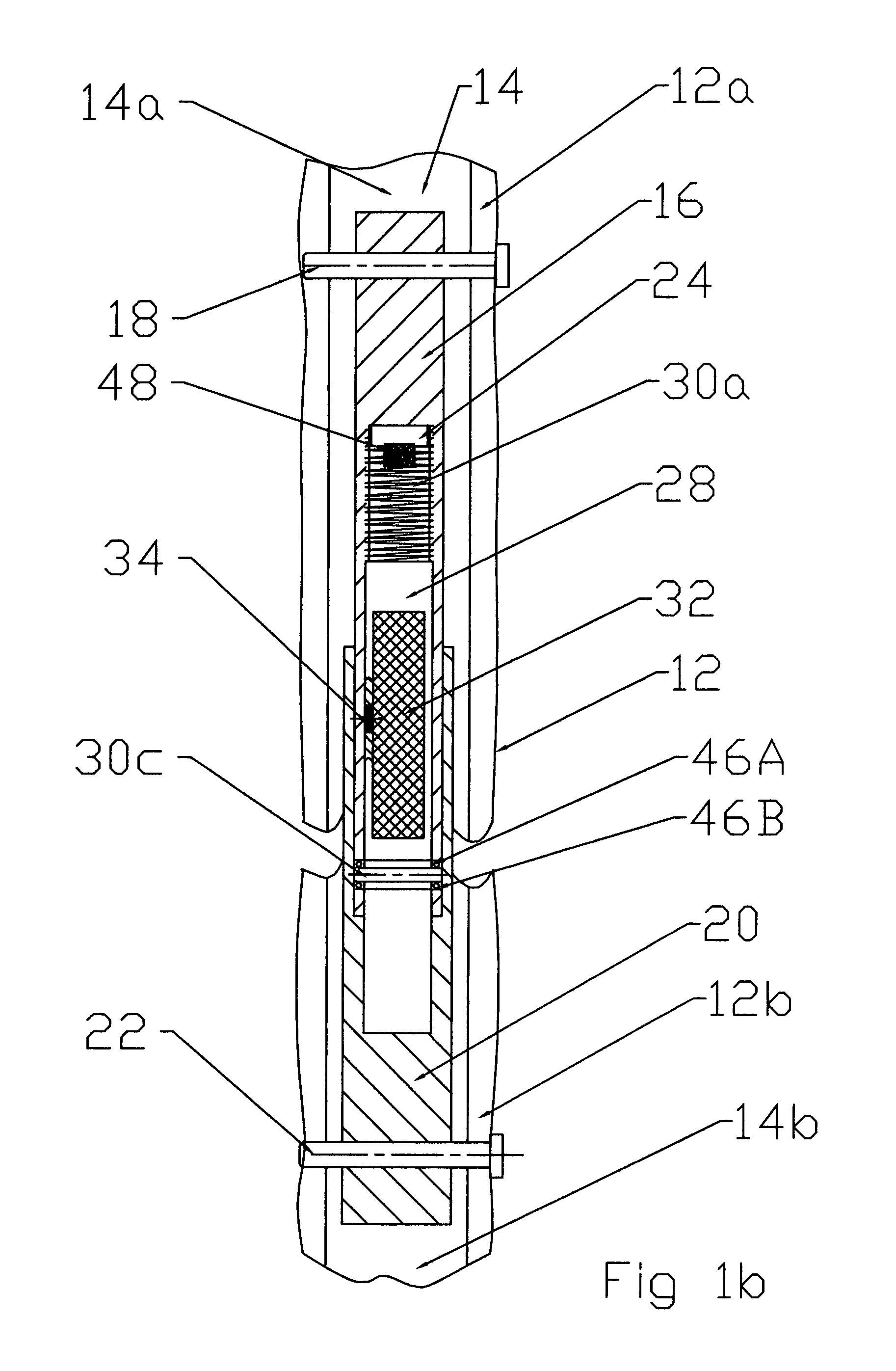
[0008]It is an object of one or more embodiments of the invention to provide a simplified, reliable implantable bone length adjustment device which moves the ends of a broken bone either away from each other or toward each other while maintaining the end regions of the fractured bone in alignment.
[0009]It is another object of one or more embodiments of the invention to provide an implantable device which is capable for use to correct spine deformation by distraction or compression of the entire spine or part of the spine.
[0010]It is yet another object of one or more embodiments of the invention to provide a bone length adjustment system which is capable of lengthening and correcting deformation of flat bones by providing distraction or compression of these flat bones while the lengthening mechanism is located outside of the engaged parts of the corrected bone.
[0016]A bone length adjustment system in accordance with the invention therefore forms a novel medical apparatus which allows flexible remote control for compression and distraction of bones under any pattern combination of compression and distraction, with any time increments and at any variable, desired incremental length adjustment during the bone lengthening procedure. It allows for bone adjustment of elongated bone, as well as for correction of spine deformation and surgical reconstruction of bones.

Problems solved by technology

A main drawback of this device is the lack of control over the lengthening of the bone, which may cause an adverse increase in the bone length.
One weakness of this device is that it provides for an essentially unidirectional motion, which can provide only an increase in length of the bone, but cannot be used to provide bone compression, i.e., a decrease in the length of the bone.

Method used


Image

  • Bi-directional bone length adjustment system
  • Bi-directional bone length adjustment system
  • Bi-directional bone length adjustment system

Examples


Embodiment Construction

[0032]Referring to the accompanying drawings wherein like reference numerals refer to the same or similar elements, one embodiment of a bone length adjustment system in accordance with the invention includes two parts, one implantable in connection with a fractured bone, e.g., in a cavity in the bone, or two separate bones and the other external of the bone or bone parts and preferably external of the body in which the bone or bone parts are situated. Several implantable parts are disclosed below and several external parts are disclosed below. Any of the implantable parts can be used with any of the external parts. Further, the implantable parts disclosed herein are only preferably used in combination with any of the external parts disclosed herein and can also be used independent thereof and possibly in connection with other external or internal parts to achieve bone length adjustment. Similarly, the external parts disclosed herein are only preferably used in combination with any o...


PUM


Abstract

Bone length adjustment method and system includes a two-part telescopic device connected to bone parts whose length between the connection points is to be adjusted, with each part of the telescopic device being secured to the bone part, and a rod with an embedded permanent magnet which is in threaded engagement at one or both of its ends with one or both of the parts of the telescopic device. The permanent magnet in the rod is excited by an external solenoid arrangement to cause a radial force to develop at the rod thereby causing it to rotate. Rotation of the rod is converted via the threads at one or both of its ends to axial motion or movement of the telescopic parts relative to each other and thereby causes an increase or decrease in the bone length depending on the direction of axial movement between the telescopic parts.

Description

FIELD OF THE INVENTION[0001]The present invention relates generally to a bone length adjustment system having a first part arranged in connection with a bone whose length is to be adjusted and a second actuating part which magnetically interacts with the first part to cause the bone length adjustment.[0002]The present invention also relates independently to an electro-magnetically actuated, telescopic implant for use in healing fractured bones and bone length adjustment.[0003]The present invention also relates independently to a bi-directional bone length adjustment system which is capable of adjusting its length in increments to provide either an increase or decrease in length, which adjustment is potentially effected under the influence of an electromagnetic field generated outside of the body in which the bone is located.BACKGROUND OF THE INVENTION[0004]A typical device used for bone lengthening consists of a special internal lengthening nail, such as a skeletal kinetic distracto...

Claims


Application Information

Patent Timeline
Patent Type & Authority Patents(United States)
IPC IPC(8): A61B17/58
CPCA61B17/663A61B17/7016A61B17/7216A61B17/7291A61B2017/00411
Inventor EKSLER, AUGUSTBLYAKHER, LUIZAKRAKHMAN, VLADIMIR
Owner EKSLER AUGUST
Learn More