
Wrist roller exercise device

a wrist roller and exercise device technology, applied in the direction of muscle exercise devices, gymnastic exercise, sport apparatus, etc., can solve the problems of less than optimal training effect, inability to attach alternate weighted implements such as dumbbells to the wrist roller exercise device rope or strap, and common fatigue of trapezoid and shoulder muscles of exercisers

Active Publication Date: 2010-07-13
EMICK DANIEL W
View PDF16 Cites 20 Cited by
  • Summary
  • Abstract
  • Description
  • Claims
  • Application Information

AI Technical Summary

Benefits of technology

[0021]Rotating said rod causes said rope to wind up onto said spool thereby lifting the weight object relative to the rod. Because said cable supports the weight of the device so that a user can focus attention on forearm, wrist, hand and finger muscles required to wind up said rope and to keep the device balanced on the cable and not on upper arm, shoulder, chest and back muscles which would otherwise be required to hold and suspend the device in said desired elevation above ground surface if not for said cable.

Problems solved by technology

The primary drawback to this traditional form of a wrist roller exercise device is that the exerciser commonly experiences trapezoid and shoulder muscle fatigue long before exhausting the targeted muscles of the forearms, wrists and hands.
The end result of this inability to direct focus energy into desired muscle groups is a less than optimal training effect.
A lesser drawback to the traditional wrist roller exercise device is the inability to affix alternate weighted implements such as dumbbells to the wrist roller exercise device rope or strap.
While many different wrist roller exercise devices have been proposed such devices each have significant drawbacks.
The devices which do not include a frame require the user to use arm, shoulder and back muscles to hold the bar in a desired location before and during the wrist rolling exercise causing fatigue to muscle groups which a wrist roller exercise device is not intended to address.
Existing devices which provide a supporting frame unduly restrict the XYZ direction in which the wrist roller exercise device can move thereby directing most of the force of the exercise to the hands and fingers and away from the wrists.

Method used


Image

  • Wrist roller exercise device
  • Wrist roller exercise device
  • Wrist roller exercise device

Examples


Embodiment Construction

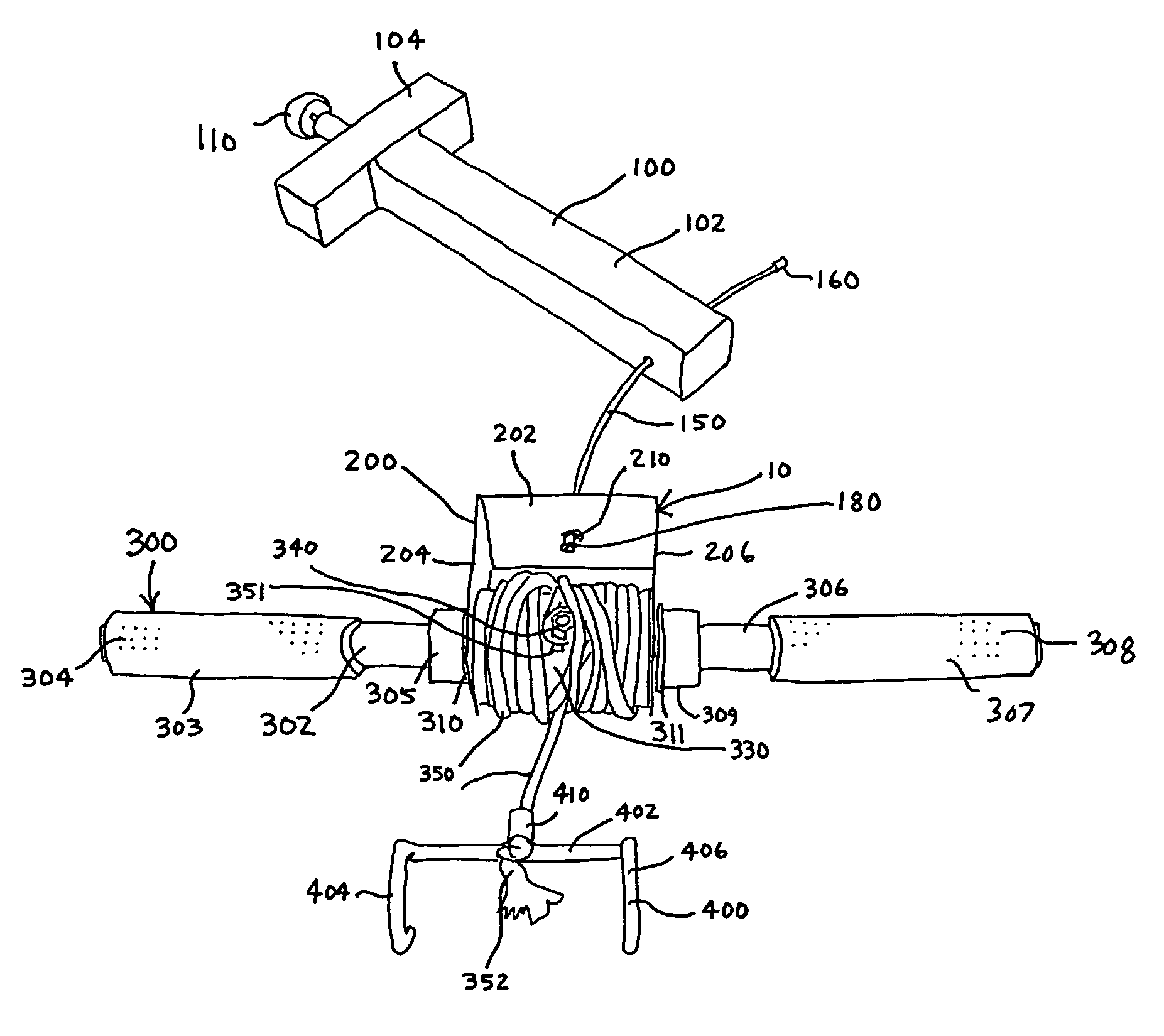
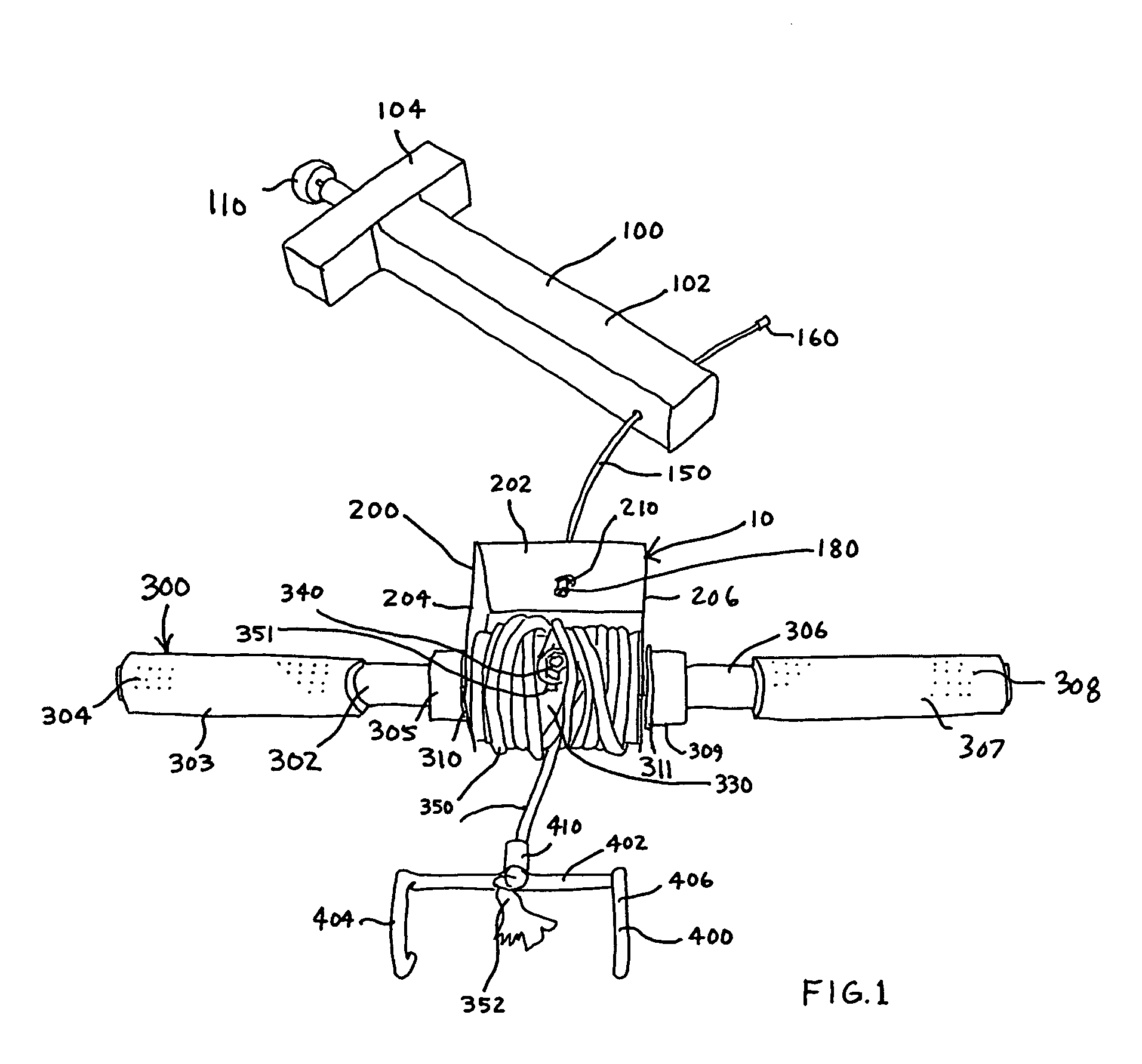
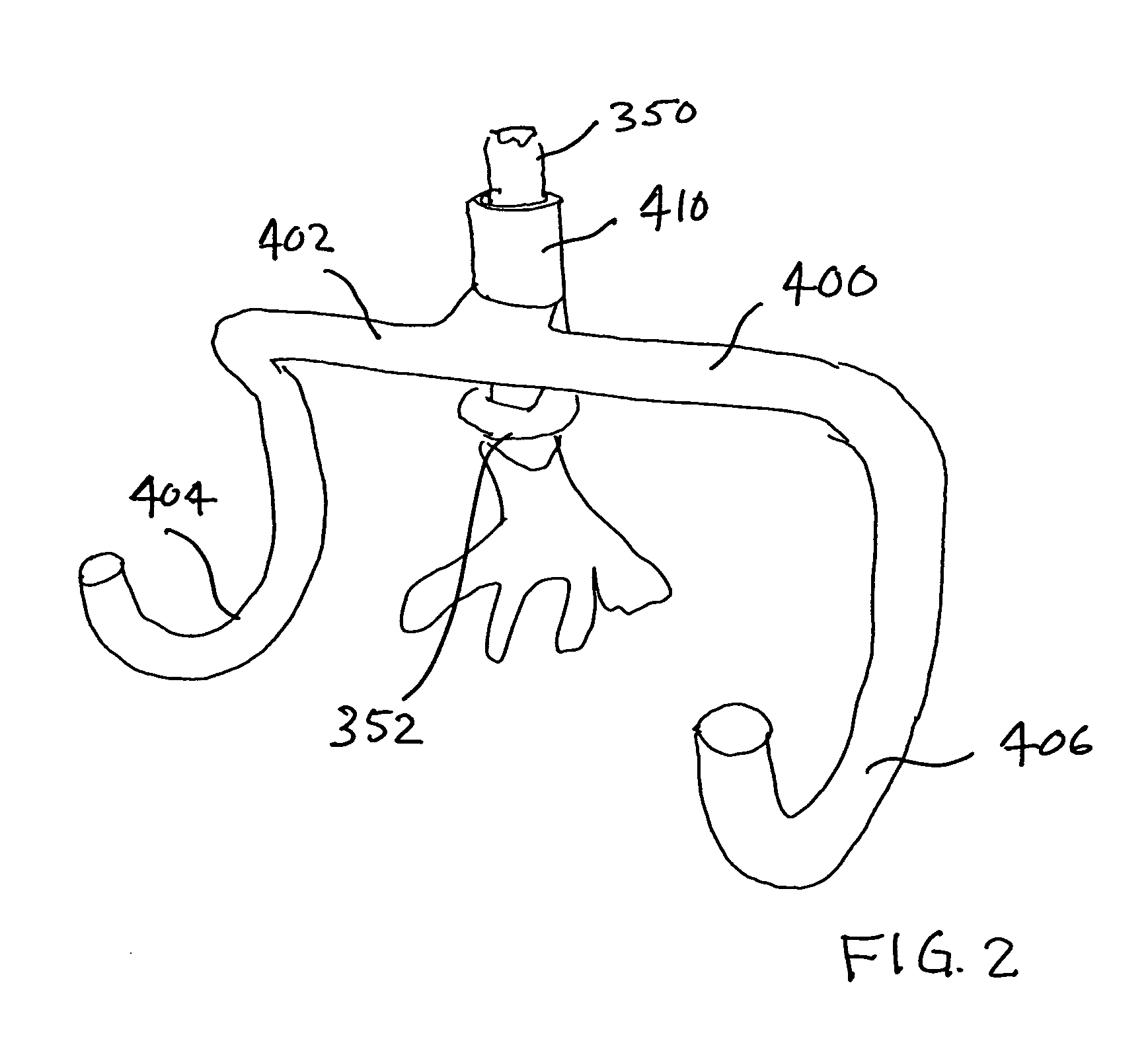
[0038]The present invention provides a wrist roller exercise device which includes a roller rod 300 which has opposite handle end portions 304 and 308 and having a central portion. The central portion is that portion located beneath the spool 330.

[0039]A spool carrier 200 is provided and preferably has a generally u-shaped configuration as shown in FIG. 6. The spool carrier 200 has a pair of opposite spaced apart parallel carrier ends 204 and 206 and has a top portion 202 which has a hole 203 therein. The hole 203 acts as a central balanced cable connection point. In carrier end 204, a rod hole 205 is provided and in carrier end 206 a rod hole 207 is provided. It will be obvious that the roller rod 300 is inserted through rod holes 205 and 207. As shown in FIG. 1, the spool carrier 200 is held in place by means of a collar 305 screw mounted onto portion 302 of the roller rod 300 and a collar 309 is mounted on portion 306 of the roller rod 300. A set screw 315 (FIG. 8) is utilized to...


PUM


Abstract

A wrist roller exercise device is provided which has a roller rod having opposite handle end portions and which has a central portion and has a spool carrier has a central balanced cable connection point. A cable is connected to the cable connection point and also connected to an elevated frame member to secure and hold the carrier at a desired elevation above ground surface. A spool is attached on the central portion of said rod member with the rod member and the spool each being rotatable relative to the spool carrier. The spool also has a rope connection thereon. A rope is provided which has a first rope end attached to the rope connection and a second rope end connected to a weight object of desired mass. The cable supports the weight of the device so that a user can focus attention on forearm, wrist, hand and finger muscles required to wind up the rope and to keep the device balanced on the cable and not on upper arm, shoulder, chest and back muscles which would otherwise be required to hold and suspend the device in the desired elevation above ground surface if not for the cable.

Description

BACKGROUND OF THE INVENTION[0001]1. Field of the Invention[0002]The present invention relates to a wrist roller exercise device. More specifically, it relates to a wrist roller exercise device having a cable suspended spool cradle to support the weight of the device to relieve the arms, shoulders and back of the user.[0003]2. Description of the Prior Art[0004]A wrist roller exercise is a common exercise for strengthening the grip and forearms of an exerciser who stands vertically with arms fully extended forward from the body and fixed and held at shoulder level. With hands gripping either side of a wrist roller exercise device (a shaft or rod with a center portion or spool for a strap or rope attachment, and gripping handles on each end) the exerciser alternatively twists the handles at opposite ends of the rod which in turn serves to coil up the rope or strap attached to the wrist roller exercise device. The effect is to cause the weighted device (weight plate, etc.) attached to t...

Claims


Application Information

Patent Timeline
Patent Type & Authority Patents(United States)
IPC IPC(8): A63B23/16
CPCA63B21/00181A63B21/153A63B23/14A63B21/0726A63B21/1627A63B2208/0204A63B2225/093
Inventor EMICK, DANIEL W.
Owner EMICK DANIEL W
Learn More