
Low profile portable derail

a portable derail and low profile technology, applied in the direction of rail engagement elements, transportation and packaging, point-signal interlocking arrangments, etc., can solve the problems of not meeting the basic purpose, and achieve the effect of being easily securable to the rail head and easy to install by a single workman

Active Publication Date: 2010-07-13
ALDON INC
View PDF10 Cites 5 Cited by
  • Summary
  • Abstract
  • Description
  • Claims
  • Application Information

AI Technical Summary

Benefits of technology

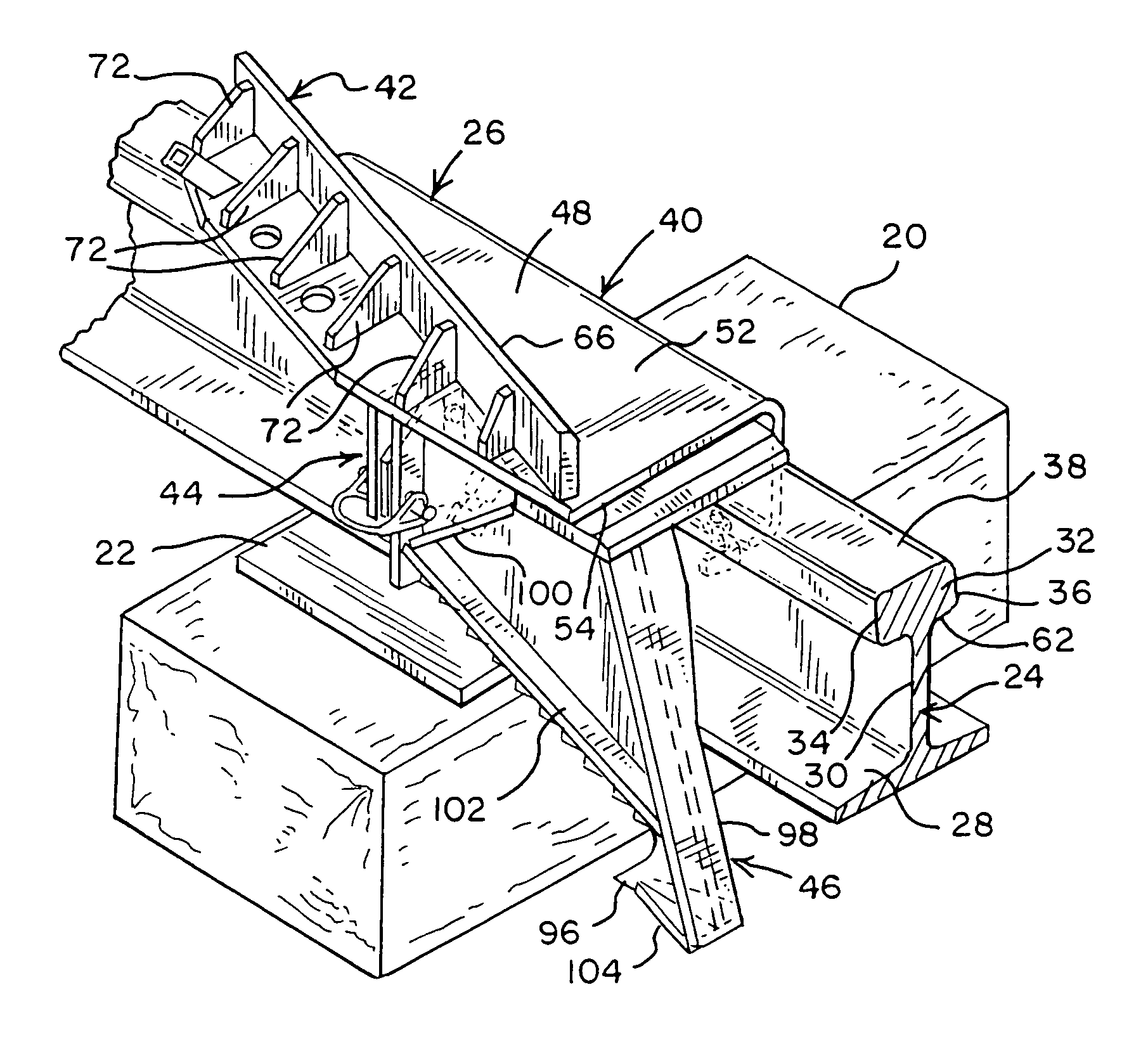
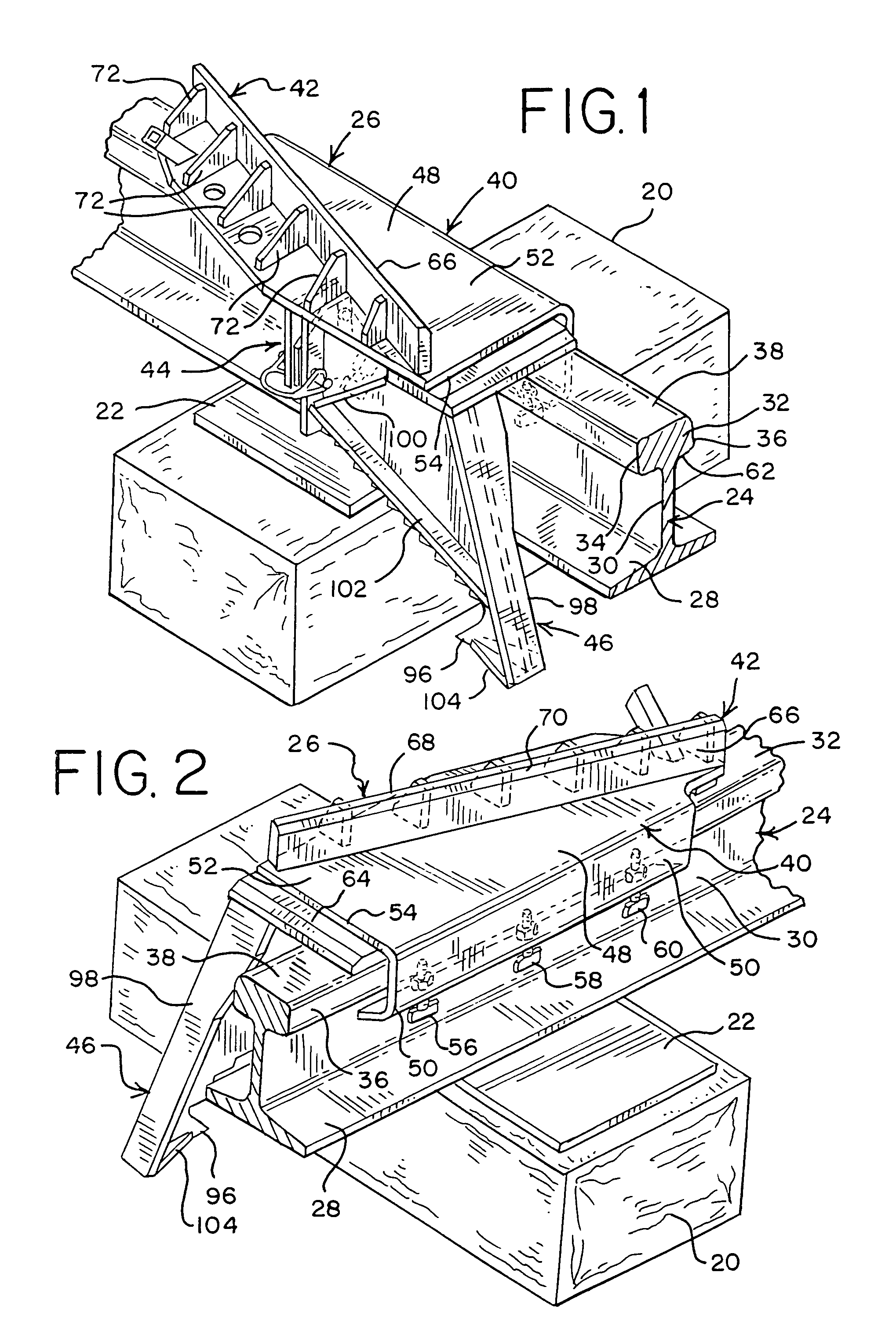
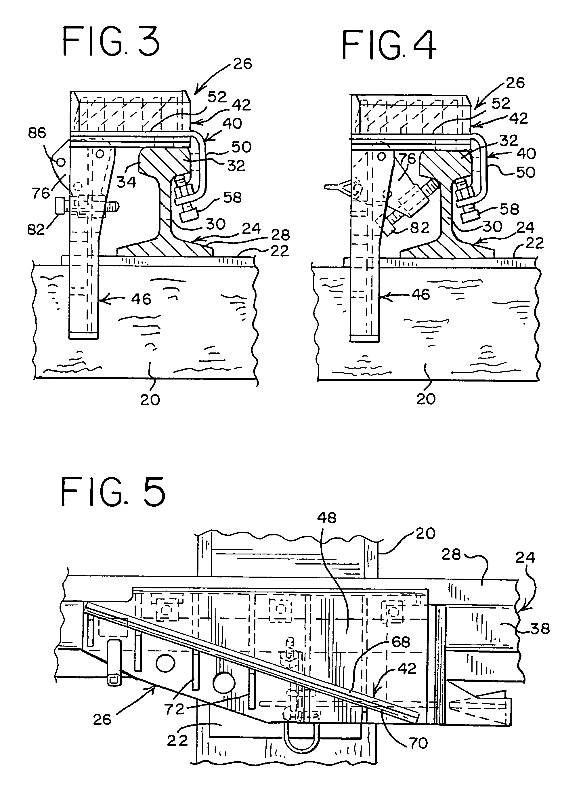
[0006]The instant derail is a low profile light weight portable derail, which may be readily installed by a single workman. It is readily securable to a railroad rail head for derailing from the rail head a flanged wheel of railroad equipment. The present derail has a monolithic derail body including a flat rider plate and a curved holding channel formed integral with an edge of the rider plate. The curved holding channel forms a continuous member with the rider plate eliminating any stress points which may cause breaking or other damage to the derail body. The curved opening of the holding channel is large enough to receive a portion of the field side of the rail head. At least three field side thumbscrews are mounted on the holding channel and are connectable with the underside of the field side of the rail head to secure the rider plate to the rail head. A substantially straight rub bar is fixed to the rider plate for engagement with a flanged wheel to be derailed from the rail head. The rub bar has a flat straight derail edge which is engagable with a wheel. A locking pad is fixed to the underside of the rider plate and is spaced away from the holding channel to allow positioning of the derail body onto the rail head. A swing arm is pivotedly mounted on the locking pad. A retainer fastener is mounted on the swing arm and is connectable with an underside of the gauge side of the rail head for holding the derail onto the rail head. A comb is connected to the derail body for engagement with a tie supporting the rail.

Problems solved by technology

A derail must have a low profile so that it is not engaged by a track clearing equipment on a locomotive and pushed along the rail thereby failing to accomplish its basic purpose of stopping movement of a locomotive past a given point.

Method used


Image

  • Low profile portable derail
  • Low profile portable derail
  • Low profile portable derail

Examples


Embodiment Construction

[0019]Referring now to the drawings, and especially to FIG. 1, a conventional railroad tie 20 is shown with a rail supporting apparatus including a baseplate or tie plate 22 mounted thereon. A conventional railroad tee rail 24 is mounted on the tie plate. A derail 26 is mounted on rail 24. Derail 26 is a specific embodiment of the present invention. Rail 24 is a conventional construction having a base 28 with a web 30 formed integral with the base. A rail head 32 is formed integral with the web. The rail head includes a gauge side 34 and an opposed field side 36. The gauge side 34 is the side adjacent to the other rail of a track consisting of a pair of rails. The rail head includes a head top 38.

[0020]Derail 26 includes a monolithic derail body 40 with a bar assembly 42 mounted on body 40 for engaging a wheel to displace the wheel from a rail head. A securing assembly 44 is mounted on the body to lock the derail body to the gauge side of the rail head. A comb assembly 46 is fixed t...


PUM


Abstract

This invention relates to a portable low profile derail which is releasably securable to a railroad rail for derailing from the rail a flanged wheel of railroad equipment. The derail has a monolithic body including a flat rider plate and an integral elongated holding channel. At least three field side fasteners are mounted on the holding channel and connectable with the rail. A substantially straight rub bar is fixed to the derail body and is set at an angle to the rail when the derail is secured to the rail. The derail includes a securing assembly which is selectively connectable to the rail for securing the derail onto the rail.

Description

FIELD OF THE INVENTION[0001]The present invention relates to a low profile portable derail used in the railroad industry. The subject derail is a lightweight derail which may be readily installed by a single workman without the need for special tools to make the installation. The derail is capable of derailing not only a railroad car, but also a locomotive. The derail may be readily removed when there is no longer the need for the derail.BACKGROUND OF THE INVENTION[0002]The utilization of derails in the railroad industry is well known and accepted. Typically, derails are used to prevent railroad equipment, such as a car or a locomotive from passing a certain point. The need for protecting a certain point from passage by equipment is created under a number of circumstances. A typical circumstance is one wherein workmen are working a car which is positioned at a given track. The requirement of safety and prevention of accidental injury to workmen is paramount. A typical and accepted m...

Claims


Application Information

Patent Timeline
IPC IPC(8): B61L19/02
CPCB61K5/06
Inventor SCHIRMER, MICHAEL L.
Owner ALDON INC
Learn More