Measurement system for determining desired/undesired ratio of wireless video signals

Active Publication Date: 2010-07-06
T MOBILE INNOVATIONS LLC
View PDF9 Cites 21 Cited by
  • Summary
  • Abstract
  • Description
  • Claims
  • Application Information

AI Technical Summary

Benefits of technology

[0007]The present invention achieves an accurate and convenient system and method for determining D / U ratios without disrupting any broadcast signals and without requiring expensive test equipment or highly specialized training of test technicians.

Problems solved by technology

Licensees at the same frequencies will operate in respective service areas, but the potential for co-channel interference still exists and the FCC has specified certain interference requirements to be met.
This type of testing creates problems because it may be necessary to shut off the transmitter repeatedly or for noticeably long periods, resulting in interruption of programming to viewers being served by the BRS licensee (which may be a cable television provider, for example).
In addition, the coordination required if multiple receive sites are being transitioned can be difficult and time consuming.
Difficulties arise when attempting to conduct measurements of desired and undesired power when both signals are present simultaneously.
This situation can be improved by shifting the frequency of the desired transmitter to increase the separation, but even with frequency shifting the proximity of the desired and undesired carrier frequencies as well as the complex voltage of the active video signal makes the D / U measurement virtually impossible using standard test equipment.
Relatively expensive equipment and / or highly skilled test operators have been required.

Method used


Image

  • Measurement system for determining desired/undesired ratio of wireless video signals
  • Measurement system for determining desired/undesired ratio of wireless video signals
  • Measurement system for determining desired/undesired ratio of wireless video signals

Examples


Embodiment Construction

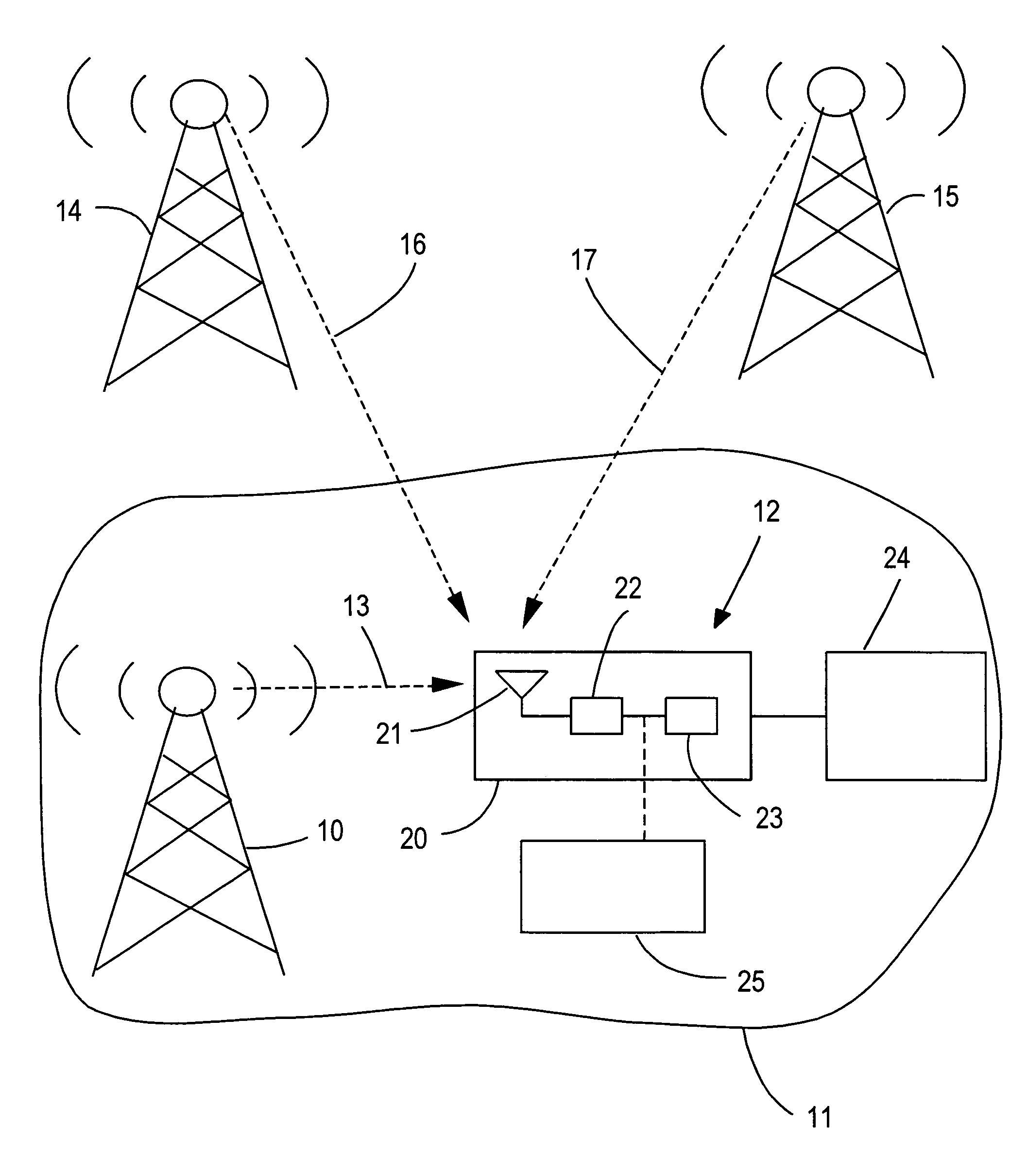
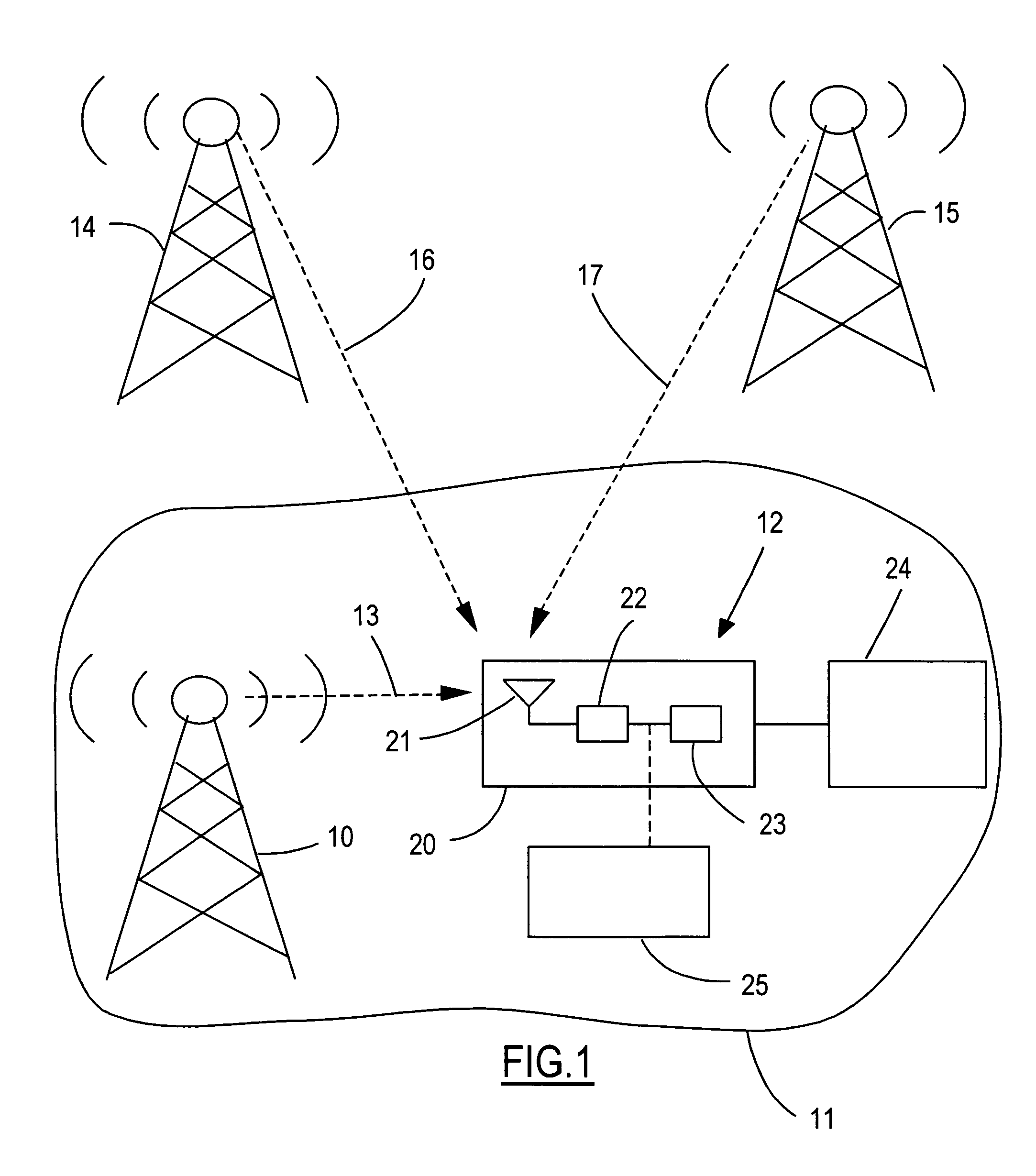
[0025]Referring now to the drawings, FIG. 1 shows a transmitter 10 with a corresponding service area 11 having a receive site 12. RF broadcast signals 13 propagate from transmitter 10 to receiving site 12. Undesired transmitters 14 and 15 in other service areas radiate broadcast signals 16 and 17, respectively, that also reach receiving site 12. The present invention measures the D / U ratio corresponding to the various broadcasts to ensure compliance with FCC regulatory levels and to facilitate adjustments by the operators of the transmitters to achieve compliance.

[0026]A receiver 20 located at receiving site 12 is connected to a video distribution system 24, such as a cable headend. Receiver 20 includes an antenna 21, a downconverter 22, and a demodulator 23. A test system 25 of the present invention is connected to the output of downconverter 22.

[0027]In order to be able to measure the much lower level undesired signals in the presence of the strong desired signals, the present inv...


PUM


Abstract

A D / U ratio is measured for desired and undesired signals in a wireless video transmission system at a shared channel frequency based on a received signal at a geographic location in proximity to regions within respective service areas for the desired and undesired signals. A video tuner demodulates the received signal to generate a baseband video signal. A leveling circuit normalizes the baseband signal. A video processor identifies horizontal sync pulses within the baseband signal, generates a sampled signal comprising the horizontal sync pulses, and removes components of the desired signal from the sampled signal to generate an undesired signal component. A D / U analyzer determines a Fourier transform having a plurality of bins in response to the undesired signal component, identifies at least one of the bins having a spectral peak corresponding to an undesired signal, and calculates the D / U ratio in response to a magnitude of the identified peak.

Description

CROSS REFERENCE TO RELATED APPLICATIONS[0001]Not Applicable.STATEMENT REGARDING FEDERALLY SPONSORED RESEARCH[0002]Not Applicable.BACKGROUND OF THE INVENTION[0003]The present invention relates in general to determining co-channel interference levels for wireless transmissions, and, more specifically, to measuring a desired / undesired ratio using portable equipment that does not require disruption of broadcasting or complicated test equipment or procedures.[0004]In connection with obligations of licensees of wireless broadcasting services, it often becomes necessary to measure various signals at potential receiving locations in order to comply with requirements designed to minimize interference between different broadcasters. For example, in the Broadband Radio Service (BRS) authorized in a 2.5 GHz band by the Federal Communications Commission in the United States, a transition is being conducted wherein licensees of the Multipoint Distribution Service (MDS) are being reassigned to fre...

Claims


Application Information

Patent Timeline
IPC IPC(8): G01R13/00
CPCH04B17/23
Inventor ARDIZZONE, GIUSEPPETENTEN, ROBERT C.
Owner T MOBILE INNOVATIONS LLC
Why Eureka
Try Eureka