
Linear compressor

a compressor and linear technology, applied in the field of linear compressors, can solve the problems of limiting the space utility of the linear compressor, high cost, complicated pumping structure, etc., and achieve the effects of improving space utility, simple oil pumping structure, and low cos

Inactive Publication Date: 2010-07-06
LG ELECTRONICS INC
View PDF5 Cites 14 Cited by
  • Summary
  • Abstract
  • Description
  • Claims
  • Application Information

AI Technical Summary

Benefits of technology

The present invention provides a linear compressor with a simplified oil pumping structure and low cost. The compressor has a simplified oil suction and discharge structure, resulting in improved space utilization. The oil suction and discharge channels are designed to produce low and high pressures, respectively, and an oil pumping device is used to create the necessary pressure difference. The oil suction and discharge valves open or close the ends of the channels to control the oil flow. The compressor is designed to be compact and cost-effective, with improved oil pumping efficiency.

Problems solved by technology

However, the above described conventional linear compressor has a problem in that it requires a number of oil pumping elements including the oil cylinder 44, the oil piston 45, and the front and rear oil springs 46 and 47, resulting in a complicated pumping structure and high cost.
This significantly restricts space utility of the linear compressor.

Method used


Image

  • Linear compressor
  • Linear compressor
  • Linear compressor

Examples


Embodiment Construction

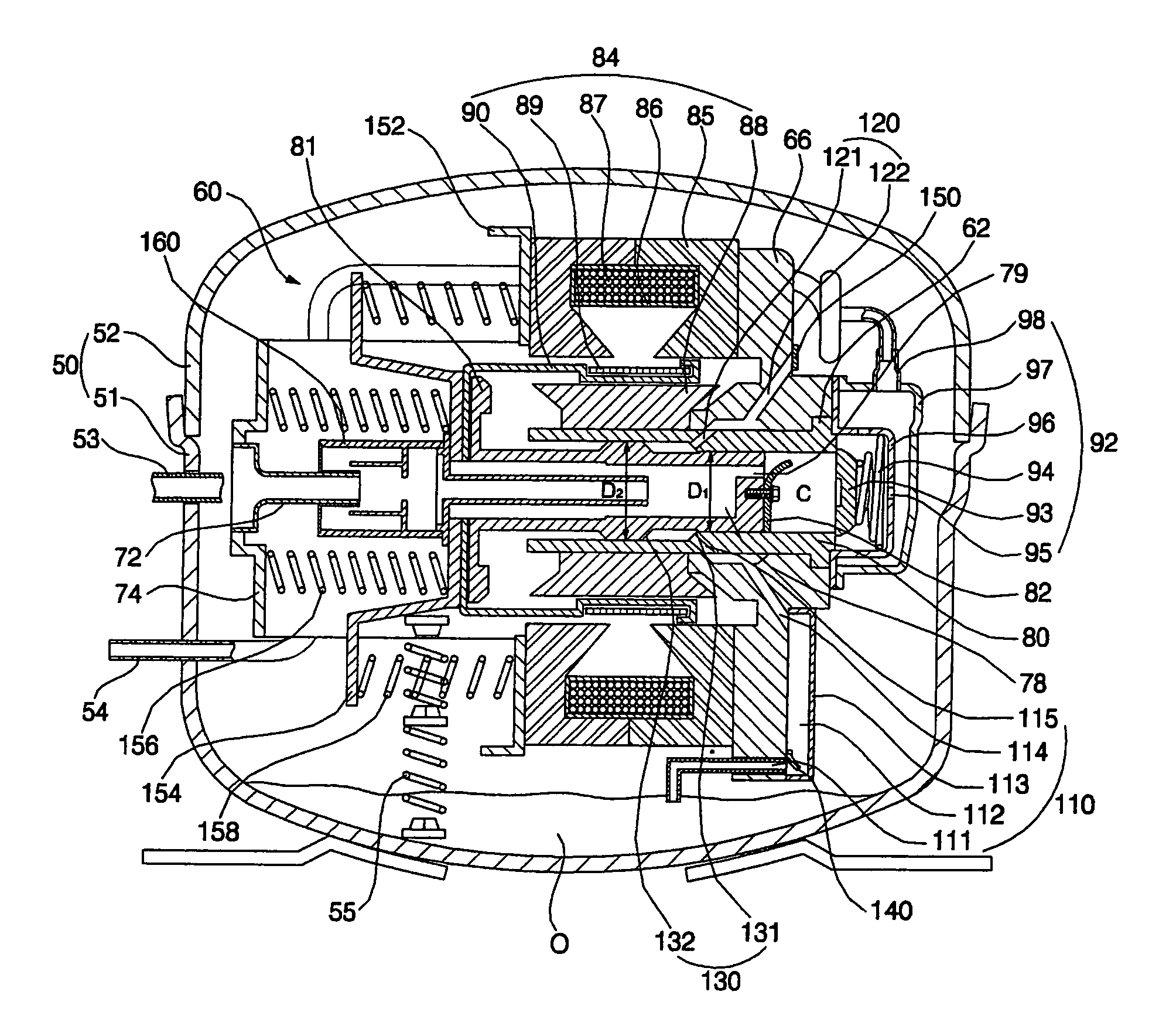
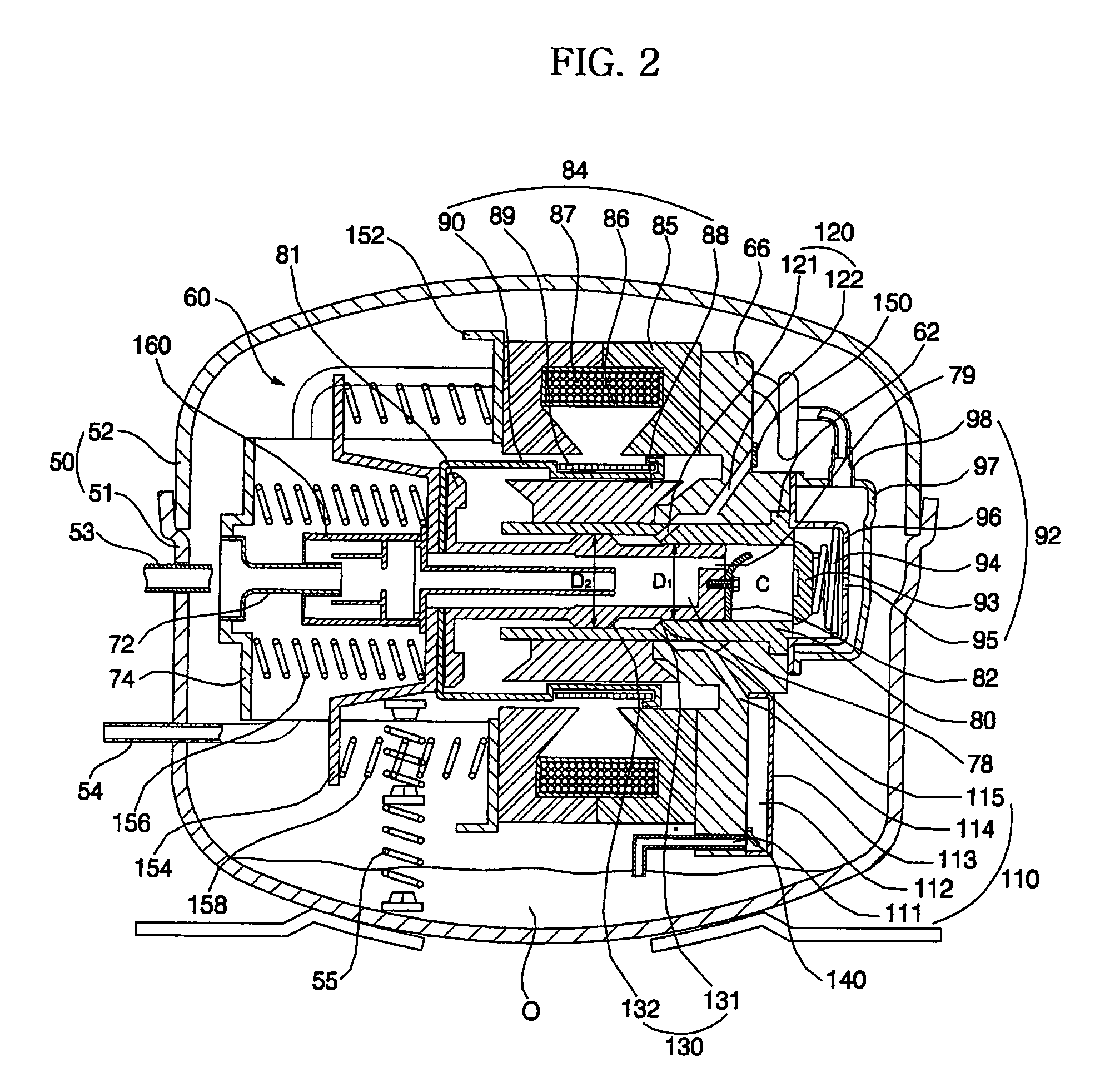
[0039]Now, a preferred embodiment of a linear compressor according to the present invention will be explained with reference to the accompanying drawings.

[0040]FIG. 2 is a cross sectional view illustrating a linear compressor in accordance with an embodiment of the present invention, upon backward movement of a piston. FIG. 3 is a cross sectional view of the linear compressor, upon forward movement of the piston.

[0041]As shown in FIGS. 2 and 3, the linear compressor of the present invention comprises a linear compressing unit 60 mounted in a shell 50 in a shock-absorbing manner.

[0042]The shell 50 is divided into a lower shell 51 having an open upper surface and an upper shell 52 configured to cover the upper surface of the lower shell 51. The lower and upper shells 51 and 52 are coupled to each other to define a hermetic space therebetween. The lower shell 51 receives oil (O) in a bottom region thereof.

[0043]A fluid suction pipe 53 and a fluid discharge pipe 54 pass into the shell 5...


PUM


Abstract

Disclosed herein is a linear compressor, which is designed in such a fashion that oil is suctioned into a space between a cylinder and a piston by a low pressure produced between the cylinder and the piston when the piston moves backward, and then is discharged to the outside by a high pressure produced between the cylinder and the piston when the piston moves forward, resulting in a simplified oil pumping structure and low cost.

Description

BACKGROUND OF THE INVENTION[0001]1. Field of the Invention[0002]The present invention relates to a linear compressor adapted to compress fluid, such as refrigerant gas, and more particularly to a linear compressor in which a high or low pressure is produced in a space between a cylinder and a piston upon reciprocation of the piston to enable oil to be supplied into the space between the cylinder and the piston.[0003]2. Description of the Related Art[0004]Generally, linear compressors are machines used to suction and compress fluid, such as refrigerant gas, and discharge the compressed fluid as a piston rectilinearly reciprocates inside a cylinder by making use of driving power of a linear motor.[0005]FIG. 1 is a sectional view illustrating a conventional linear compressor.[0006]As shown in FIG. 1, the conventional linear compressor comprises a shell 2, a liner compressing unit 10, and an oil pump 20. The shell 2 receives oil O in a bottom region thereof, and the linear compressing u...

Claims


Application Information

Patent Timeline
Patent Type & Authority Patents(United States)
IPC IPC(8): F04B17/00F04B17/04F04B35/04
CPCF04B35/045F04B39/0284F04B39/0276F04B39/0238F04B39/10
Inventor LEE, JONG KOOSONG, GYE YOUNG
Owner LG ELECTRONICS INC
Learn More