
Plastic container with horizontally oriented panels

a technology of horizontal orientation and plastic containers, applied in the field of blow-molded containers, can solve the problems of less resistance of containers to deformation, and achieve the effect of stable geometry

Inactive Publication Date: 2010-07-06
AMCOR RIGID PLASTICS USA
View PDF47 Cites 22 Cited by
  • Summary
  • Abstract
  • Description
  • Claims
  • Application Information

AI Technical Summary

Benefits of technology

"The present invention provides a plastic container with pressure-responsive panels that can change their shape to adapt to changes in pressure within the container. The panels are located in the side wall of the container and are separated from each other by a smoothly joined ring element or a series of vertical posts. The container is stable and can withstand typical hot-fill conditions and storage without losing its shape. The technical effects of the invention include improved stability, flexibility, and adaptability of the container to changes in pressure, as well as a unique and stable geometry that is achieved through the use of pressure-responsive panels in the side wall."

Problems solved by technology

It is well recognized that the exposure of any plastic container to elevated temperatures tends to soften the plastic material and make the container less resistant to deformation.

Method used


Image

  • Plastic container with horizontally oriented panels
  • Plastic container with horizontally oriented panels
  • Plastic container with horizontally oriented panels

Examples


Embodiment Construction

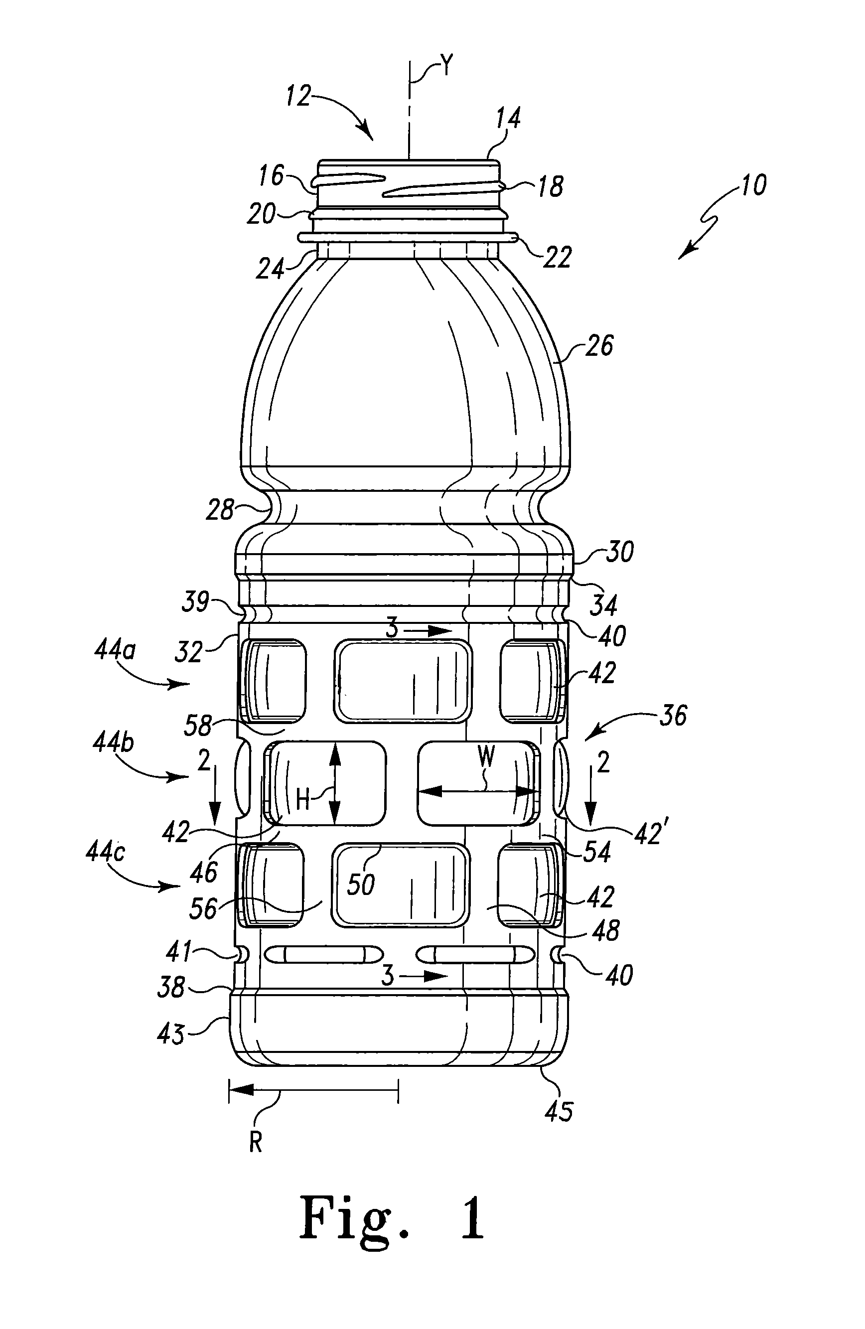
[0023]A container 10 of the present invention is shown in FIG. 1 to be generally symmetric about a vertical axis Y, and has an open mouth 12 surrounded by a lip 14 intended to cooperate with a cap, not shown, to seal the container and contents. A cap-engaging finish 16 is located below the lip 14, which is illustrated to have the form of a spiral thread 18. The particular form of the finish 16 can be varied to include a range of thread styles or even be replaced with any number of non-threaded finishes designed to accept a crown type or other cap. A pilfer ring 20 can be located immediately below the finish 16 to engage a pilfer-indicating band of a cap. A support ring 22 can be provided below the pilfer ring 20 that facilitates handling of the container 10 as well as the handling of the parison or preform from which the container 10 is formed. A neck portion 24 is located immediately below the support ring.

[0024]A shoulder portion 26 extends outward and downward from a lower margin...


PUM


Abstract

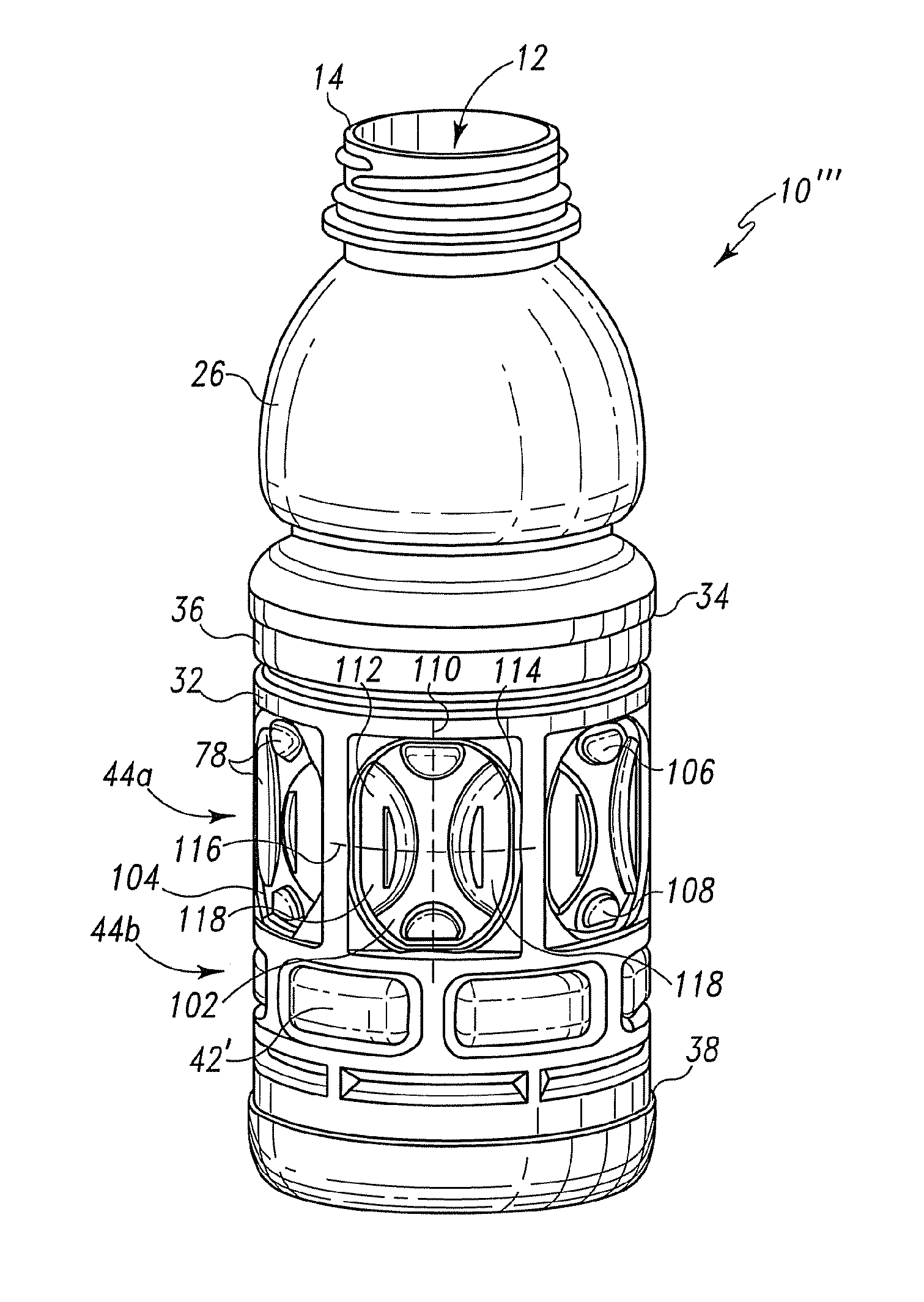
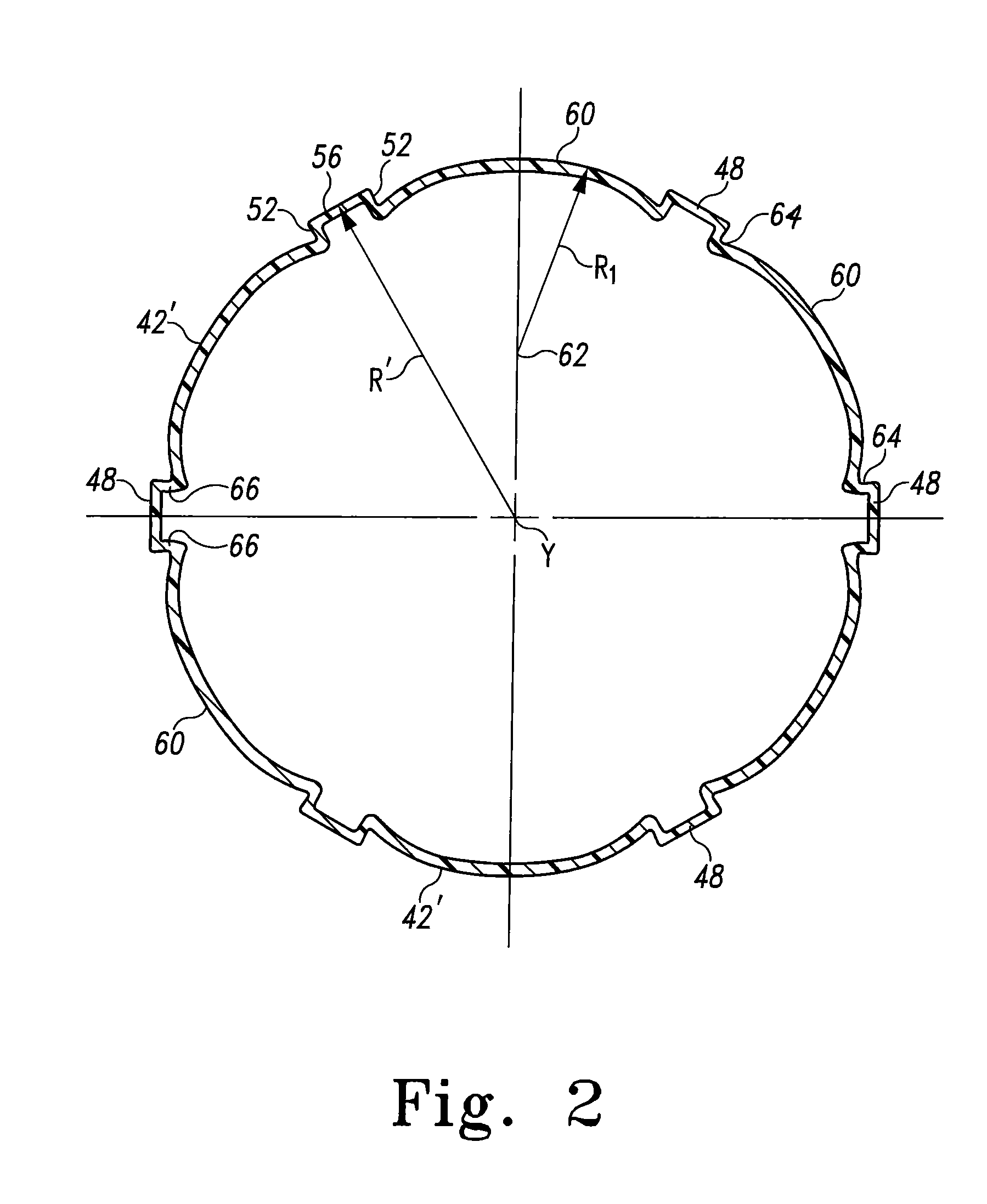
A molded polymeric container generally symmetric about a vertical axis includes at least two rows of panels disposed circumferentially around the body, the panels having central portions that are sufficiently flexible to be dimensionally responsive to changes in pressure within the container. At least one row of the panels has a margin having a horizontal width exceeding the vertical height, thus being laterally elongate with a height / width aspect ratio of less than one. The pressure responsive central portion of each laterally elongate panel is a smooth outwardly projecting dome from a peripheral root of a generally radially projecting wall defining the margins of circumferential rings and posts separating the panels. Panels in another row can have an ovate step connecting the perimeter of the panel to the central portion of the panel. Outward protrusions can be provided within the central portion to provide support for a surrounding label.

Description

CROSS-REFERENCE TO RELATED APPLICATIONS[0001]This application is a Continuation-In-Part of application Ser. No. 11 / 035,790 filed Jan. 14, 2005, now U.S. Pat. No. 7,243,808 issued Jul. 17, 2007.BACKGROUND[0002]1. Technical Field[0003]The present invention is directed to molded plastic bottles capable of being filled with liquids at elevated temperature. The present invention is particularly directed to such containers having at least two vertically spaced circumferential rows of pressure or vacuum responsive panels.[0004]The present invention particularly relates to blow-molded containers of biaxially oriented thermoplastic materials such as polyethylene terephthalate that are designed to be filled with a hot liquid or semi-liquid product and hermetically sealed, generally referred to as thin-walled, hot-fill containers. The invention pertains to improvements in the design of such containers intended to achieve a container side wall construction that provides enhanced support during ...

Claims


Application Information

Patent Timeline
Patent Type & Authority Patents(United States)
IPC IPC(8): B65D1/02B65D1/46
CPCB65D1/0223B65D79/02Y10S215/90
Inventor LIVINGSTON, JOHN J.GATEWOOD, ERIK E.TYREE, BRIAN D.STOWITTS, ADAM P. S.
Owner AMCOR RIGID PLASTICS USA
Learn More