Clothing managing apparatus
a management apparatus and clothing technology, applied in the direction of other washing machines, cleaning using liquids, textiles and paper, etc., can solve the problems of difficult mold making of the control panel, damage/breakage of the stopping protrusion, and wobble of the stopping protrusion, so as to eliminate the burr or other disadvantages resulting from the undercutting and the effect of smooth coupling
- Summary
- Abstract
- Description
- Claims
- Application Information
AI Technical Summary
Benefits of technology
Problems solved by technology
Method used
Image


Examples
first embodiment
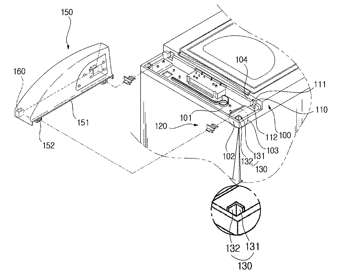
[0028]FIG. 1 is an exploded perspective view showing an upper portion of a washing machine according to the present invention.
[0029]Referring to FIG. 1, the washing machine includes a top cover 100 on an upper portion. The top cover 100 includes a panel receiving portion 101 on a rear portion. The panel receiving portion 101 receives a control panel 150. The top cover 100 includes panel coupling protrusions 130 and holders 120 to hold the control panel 150 on the panel receiving portion 101.
[0030]The top cover 100 includes side portions 103 stepped down to a predetermined depth. The side portions 103 are connected with a rear portion 102 of the top cover 100 to form the panel receiving portion 101. Therefore, the panel receiving portion 101 is lower than a front side of the top cover 100 by a predetermined depth. The panel receiving portion 101 is formed to receive the control panel 150.
[0031]The panel receiving portion 101 includes holder front coupling holes 110 in a front portion...
second embodiment
[0059]FIG. 7 is a perspective view showing a control panel before the control panel is coupled to a top cover according to the present invention.
[0060]Referring to FIG. 7, panel coupling protrusions 130 are protrude from a top cover 100 and have a predetermined curvature. Each of the panel coupling protrusion 130 includes a right sub protrusion 133 curved to the right and a rear sub protrusion 134 curved to the rear side. The light sub protrusion 133 and the rear sub protrusion 134 are connected with each other.
[0061]When assembled, the panel coupling protrusions 130 are inserted into protrusion coupling hole portions 160. Each of the protrusion coupling hole portion 160 includes a corner 163 of the a control panel 150 and an inner hole wall 165. The inner hole wall 165 is curved with a predetermined curvature. The inner hole wall 165 and the corner 163 define a hole 166 to receive the panel coupling protrusion 130. Preferably, the pre-determined curvature of the inner hole wall 165...
third embodiment
[0063]FIG. 8 is a perspective view showing a control panel before the control panel is coupled to a top cover according to the present invention.
[0064]Referring to FIG. 8, panel coupling protrusions 130 are protrude from a top cover 100. Each of the panel coupling protrusion 130 includes a horizontal sub protrusion 135 and a vertical sub protrusion 136. The horizontal sub protrusion 135 has a front-facing surface and a back-facing surface, and the vertical sub protrusion 135 is connected to the back-facing surface of the horizontal sub protrusion 135. In detail, the vertical sub protrusion 136 is connected to the back-facing surface of the horizontal sub protrusion 135 at a predetermined position between both sides of the horizontal sub protrusion 135. The horizontal and vertical sub protrusions 135 and 136 are formed in an approximate T-shape.
[0065]When assembled, the panel coupling protrusions 130 are inserted into protrusion coupling hole portions 160. In this position, the front...
PUM
 Abstract
Description
Claims
Application Information
 - R&D
- Intellectual Property
- Life Sciences
- Materials
- Tech Scout
- Unparalleled Data Quality
- Higher Quality Content
- 60% Fewer Hallucinations
Browse by: Latest US Patents, China's latest patents, Technical Efficacy Thesaurus, Application Domain, Technology Topic, Popular Technical Reports.
© 2025 PatSnap. All rights reserved.Legal|Privacy policy|Modern Slavery Act Transparency Statement|Sitemap|About US| Contact US: help@patsnap.com