System, method and apparatus for direct head-disk clearance measurement by slider vibration and fly height calibration

a slider and vibration technology, applied in the field of direct measurement of head-disk clearance by slider vibration and fly height calibration, can solve the problems of insufficient calibration, inability to accurately measure the clearance of the head-disk, and introduce considerable errors, and achieve the effect of flying height performance of the disk driv

Inactive Publication Date: 2010-05-25
WESTERN DIGITAL TECH INC
View PDF17 Cites 10 Cited by
  • Summary
  • Abstract
  • Description
  • Claims
  • Application Information

AI Technical Summary

Benefits of technology

[0009]A head flying over a disk is a relatively linear system with certain resonance modes in the frequency range of about 50 kHz to 300 kHz. The modes can be excited and the slider will under go simple sinusoidal motion. In particular, the P2 mode, where the trailing edge of the slider vibrates vertically, may be used to detect the vertical fly height clearance between the head and disk. Again, the amplitude of the vibration may be measured with an LDV. The calibration of the LDV measurement is determined by an internal clock and the speed of light and is very accurate. The slider vibrates freely until it contacts the disk. The contact may be detected in several ways, such as with an arm electronics sensor mounted on the slider, such as applications for glide heads. The amplitude of the vibration, mean to peak, at the head and disk contact is the fly height clearance.

Problems solved by technology

However, it is calculated against a known scale and is in need of calibration.
Bump calibration with speed sensitive airbearing or TFC protrusion depends on bump characterization and data extrapolation which can introduce considerable error.

Method used


Image

  • System, method and apparatus for direct head-disk clearance measurement by slider vibration and fly height calibration
  • System, method and apparatus for direct head-disk clearance measurement by slider vibration and fly height calibration
  • System, method and apparatus for direct head-disk clearance measurement by slider vibration and fly height calibration

Examples


Embodiment Construction

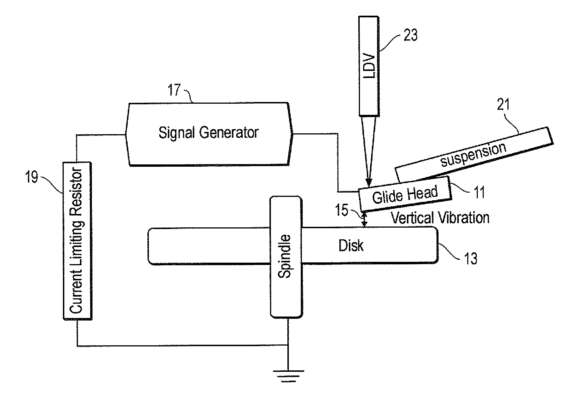
[0016]Referring to FIGS. 1-4, embodiments of a system, method and apparatus for measuring head-disk clearance by slider vibration and calibrating the fly height performance of sliders in disk drives. Fly height may be defined as the absolute distance from a reference point on the slider, usually the lowest point on the slider, to the mean of the disk topography. Head-disk clearance may be defined as the allowable fly height reduction before the slider makes contact with the disk.

[0017]In one embodiment (e.g., FIG. 1), the fly height clearance may be measured with a pico glide head 11 relative to a disk 13. The vibration 15 of the head 11 at, for example, the P2 resonance mode is excited by an electrostatic force. Such electrostatic force may be provided by a signal generator 17 and current limiting resistor 19. Other means of excitation can also be used, for example, using PZT crystals mounted on the suspension 21.

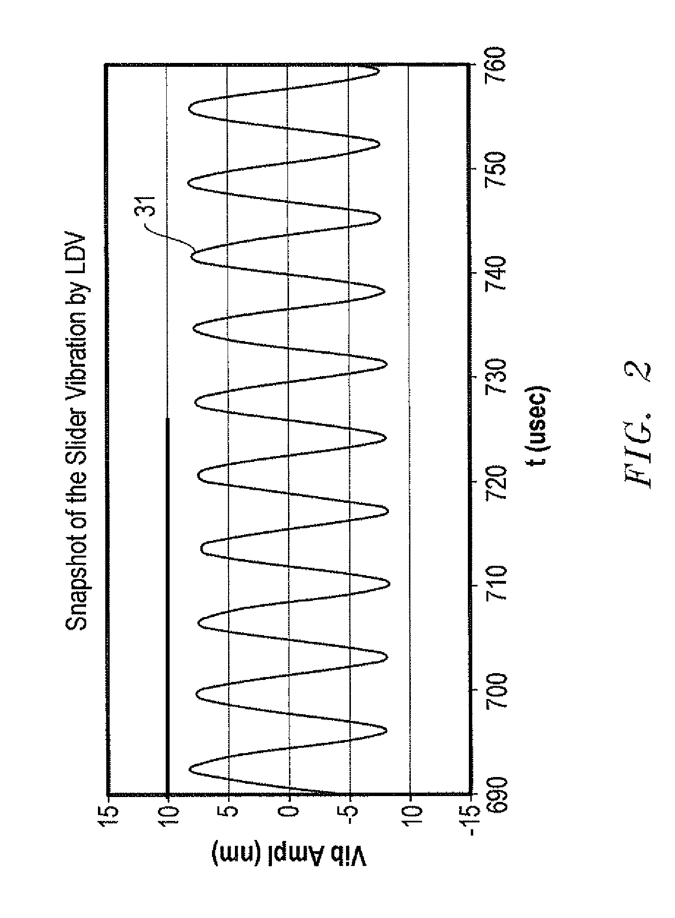
[0018]The plot 31 of FIG. 2 shows a snapshot of a slider's P2 vibrati...


PUM

PropertyMeasurementUnit
fly heightsaaaaaaaaaa
frequencyaaaaaaaaaa
heightaaaaaaaaaa

Abstract

A method models and calibrates the fly height of a slider above the disk for disk drives. The calibration scheme uses the Wallace spacing loss equation and laser doppler velocimetry to predict fly height and detect the actual fly height of the slider. The slider is vibrated at selected resonances, such as by capacitive coupling to the disk, and the fly height is gradually reduced. In one version, contact between the slider and disk may be detected using an arm electronics sensor. The amplitude of mean-to-peak, vibration detection is used as an indication of the actual fly height and to calibrate the modeled fly height.

Description

BACKGROUND OF THE INVENTION[0001]1. Technical Field[0002]The present invention relates in general to measuring parameters of sliders and disks used in magnetic storage devices and, in particular, to a system, method and apparatus for measuring head-disk clearance by slider vibration and calibrating the fly height performance of sliders in disk drives.[0003]2. Description of the Related Art[0004]In a magnetic disk recording system, a slider containing magnetic transducers for reading and writing magnetic transitions is urged toward the rotating disk by a suspension. As the disk rotates an air bearing develops under the slider and causes it to fly above the disk. The distance between the slider and the disk surface is the clearance. The disk typically includes a thin film overcoat and a set of thin films which include one or more ferromagnetic layers in which information is recorded. A disk drive can contain multiple disks and multiple sliders.[0005]Lower slider fly heights are requir...

Claims


Application Information

Patent Timeline
Patent Type & Authority Patents(United States)
IPC IPC(8): G11B21/02G11B27/36
CPCG11B5/6005
Inventor DUAN, SHANLINHE, JIZHONGHOPKINS, JOHN STEPHENLUO, YANSHENG
Owner WESTERN DIGITAL TECH INC
Why Eureka
Try Eureka