
Fuel injection control apparatus and method for internal combustion engine

a control apparatus and internal combustion engine technology, applied in the direction of electrical control, process and machine control, instruments, etc., can solve the problems of inability to achieve the desired air-fuel ratio, complex control logic, and inability to appropriately control the amount of fuel actually used in the combustion chamber, etc., to achieve the effect of less apt to vaporiz

Active Publication Date: 2010-05-25
HONDA MOTOR CO LTD
View PDF14 Cites 3 Cited by
  • Summary
  • Abstract
  • Description
  • Claims
  • Application Information

AI Technical Summary

Benefits of technology

The present invention provides a fuel injection control apparatus and method for an internal combustion engine that can appropriately control the amount of fuel injected from an in-cylinder fuel injection valve and a port fuel injection valve while considering the fuel transport behavior as the whole cylinder. This approach simplifies the control logic and allows for stable air-fuel ratio control regardless of the operating condition of the engine. The apparatus and method calculate the required in-cylinder and port injection amounts, as well as the fuel behavior parameters indicative of the transport behavior of the fuel injected from the respective valves. By determining the net in-cylinder and port injection amounts, the control apparatus and method can accurately control the air-fuel ratio to a desired value.

Problems solved by technology

However, in the conventional fuel injection control apparatus, a correction against the sticking is made only for a fuel injected from the port fuel injection valve, so that a fuel transport behavior of the whole cylinder, including the sticking of a fuel injected from the in-cylinder fuel injection valve, is not reflected.
As a result, the amount of fuel actually used in the combustion in the combustion chamber cannot be appropriately controlled, failing to achieve a desired air-fuel ratio.
Also, in this fuel injection control apparatus, the correction against the sticking is performed exclusively in an operating condition in which the proportion of the port injection amount is increasing, so that an appropriate fuel injection amount reflecting a fuel transport behavior cannot be set in other operating conditions of the internal combustion engine.
Further, since fuel injection amounts are set by control approaches different from each other between the operating condition in which the proportion of the port injection amount is increasing and other operating conditions, the entire control logic is complicated, and the air-fuel ratio is more likely to vary before and after switching between the control approaches.

Method used


Image

  • Fuel injection control apparatus and method for internal combustion engine
  • Fuel injection control apparatus and method for internal combustion engine
  • Fuel injection control apparatus and method for internal combustion engine

Examples


Embodiment Construction

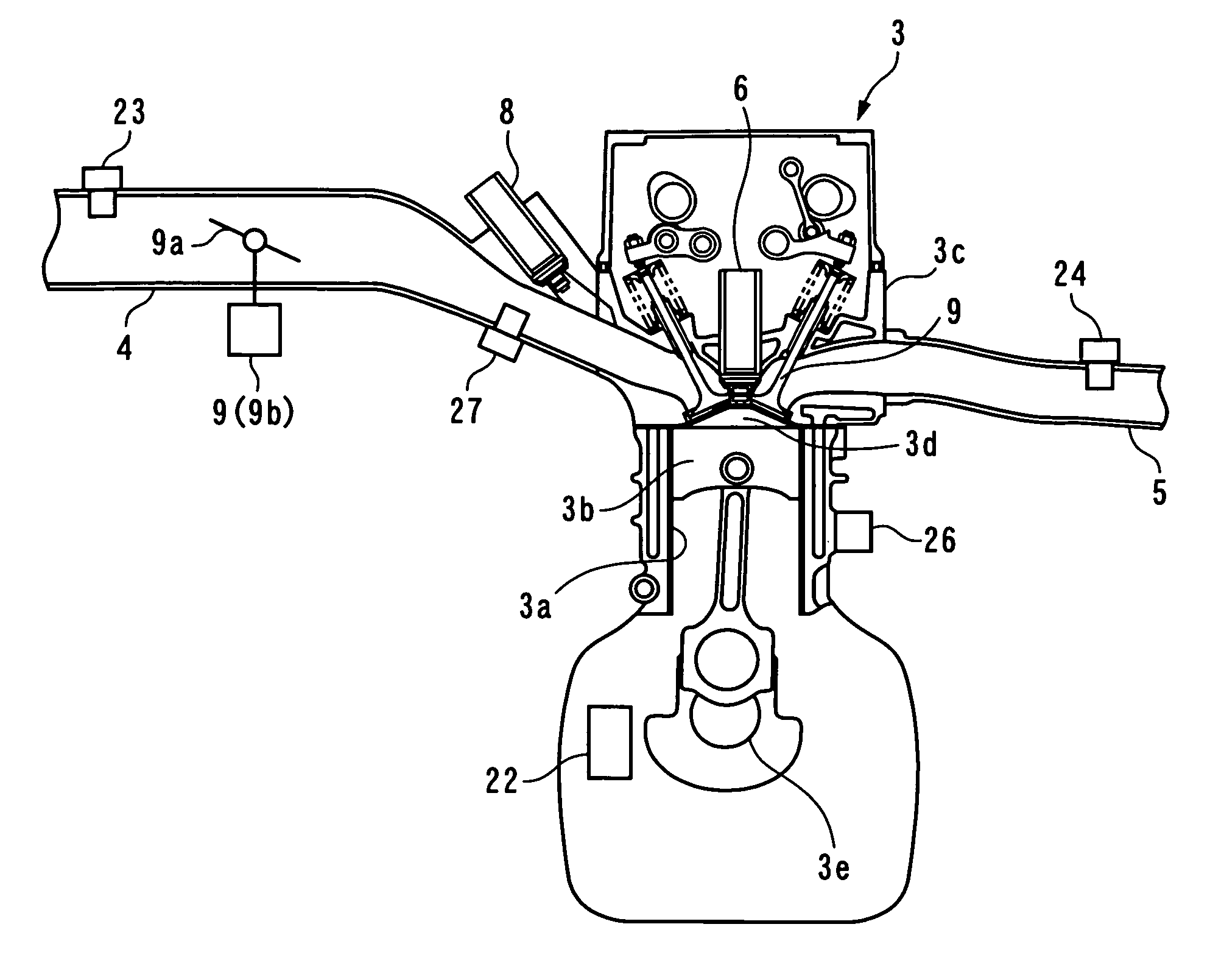
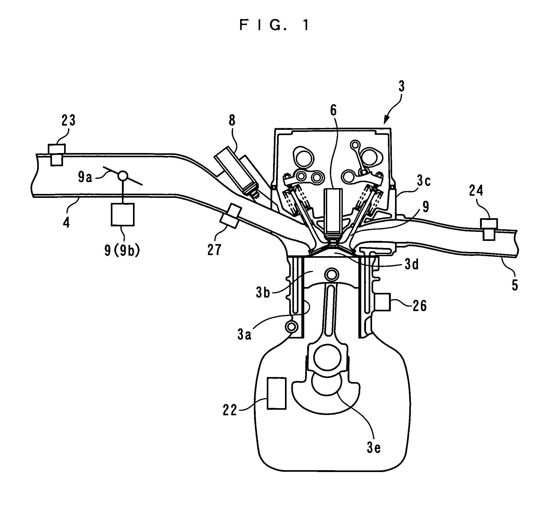
[0038]In the following, a preferred embodiment of the present invention will be described with reference to the drawings. FIG. 1 generally shows an internal combustion engine 3 to which a fuel injection control apparatus 1 according to this embodiment is applied. The internal combustion engine (hereinafter referred to as the “engine”) 3 is, for example, an in-line four-cylinder type four cycle gasoline engine which is equipped in a vehicle (not shown).

[0039]A cylinder head 3c of the engine 3 is connected to an intake pipe 4 (intake system) and an exhaust pipe 5 for each cylinder 3a, and an in-cylinder fuel injection valve 6 and an ignition plug 7 (see FIG. 2) are attached to face a combustion chamber 3d (only one each of which is shown in FIG. 1). This in-cylinder fuel injection valve 6 is configured to inject a fuel in the vicinity of an ignition plug 7 within the cylinder 3a. Also, a valve opening time and valve opening / closing timings of the in-cylinder fuel injection valve 6, as...


PUM


Abstract

A fuel injection control apparatus and method for an internal combustion engine are provided for appropriately controlling the amounts of fuel supplied from an in-cylinder fuel injection valve and a port fuel injection valve to a cylinder in a simple control approach while satisfactorily reflecting a fuel transport behavior as a whole cylinder. An ECU calculates a required in-cylinder injection amount and a required port injection amount, calculates an in-cylinder injected fuel behavior parameter of a fuel from the in-cylinder fuel injection valve and a port injected fuel behavior parameter of the fuel from the port fuel injection valve, a net in-cylinder injection amount in accordance with the in-cylinder and port injected fuel behavior parameters based on the required in-cylinder injection amount, and a net port injection amount in accordance with the in-cylinder and port injected fuel behavior parameters based on the required port injection amount.

Description

BACKGROUND OF THE INVENTION[0001]1. Field of the Invention[0002]The present invention relates to a fuel injection control apparatus and method for an internal combustion engine which is supplied with a fuel by an in-cylinder fuel injection valve for injecting the fuel into a cylinder, and a port fuel injection valve for injecting the fuel into an intake system including an intake port.[0003]2. Description of the Prior Art[0004]Conventionally, as this type of fuel injection control apparatus for an internal combustion engine, one described, for example, in Laid-open Japanese Patent Application No. 2005-337102 is known. In this fuel injection control apparatus, the proportion of an in-cylinder injection amount injected from an in-cylinder fuel injection valve to a port injection amount injected from a port fuel injection valve is set in accordance with a detected operating condition of an internal combustion engine. Also, when the proportion of the port injection amount decreases whil...

Claims


Application Information

Patent Timeline
Patent Type & Authority Patents(United States)
IPC IPC(8): F02B1/00F02B7/00
CPCF02D41/047F02D41/3041F02D41/3094F02D41/3047F02D41/3029F02D2200/021F02D2041/3052F02D2041/389
Inventor SHINOHARA, TOSHINARIOGAWA, KENKITAMURA, TORUITOGA, CHIHO
Owner HONDA MOTOR CO LTD
Learn More