
Automatic container coupling tool

a container coupling and automatic technology, applied in the field of coupling tools, can solve the problems of considerable labor maneuverability might be required for handling the coupler, and inefficient and slow practice, and achieve the effect of preventing displacement without excessive manual maneuverability, efficient and reliabl

Inactive Publication Date: 2010-05-25
KUSN LUCKY SEA IND
View PDF1 Cites 3 Cited by
  • Summary
  • Abstract
  • Description
  • Claims
  • Application Information

AI Technical Summary

Benefits of technology

"The present invention provides an automatic container coupler for over stacking shipping containers. The coupler has a simple structure and is designed to easily detach two stacked containers without complicated manual procedures. The coupler includes a bottom engager and a top guiding protrusion that securely interlock with the containers, allowing them to be stacked together. The coupler is efficient, reliable, and cost-effective. It can be used with a variety of container types and can be easily manufactured and installed. The coupler is also adaptable for over stacking containers, ensuring secure and reliable connection between them."

Problems solved by technology

However, the conventional container couplers are inefficient and slow in practices for stacking an upper shipping container onto a lower shipping container.
Needless to say, considerable labor maneuverability might be required for handling the couplers in shipping process, and the safety issue would be one of the main arguments for how to couple and stack shipping containers.
Besides inefficient and slow in practice, a prominent drawback of the conventional hand-coupled system is relatively unsafe to workers.
On the other hand, a conventional coupler is made up of many parts, which leads to a complicated structure of such kind of coupler.
As a result, the maintenance and reparation of such kind of couplings would be difficult and expectably expensive.

Method used


Image

  • Automatic container coupling tool
  • Automatic container coupling tool
  • Automatic container coupling tool

Examples


Embodiment Construction

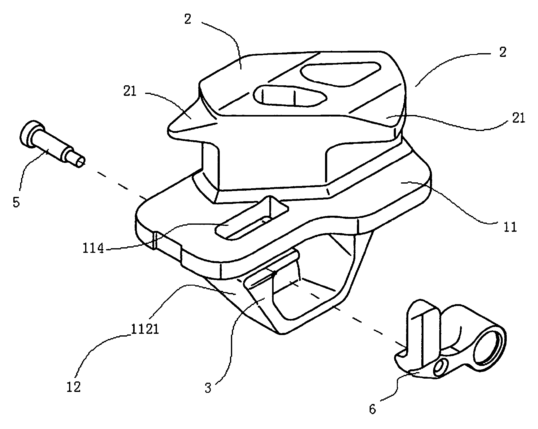
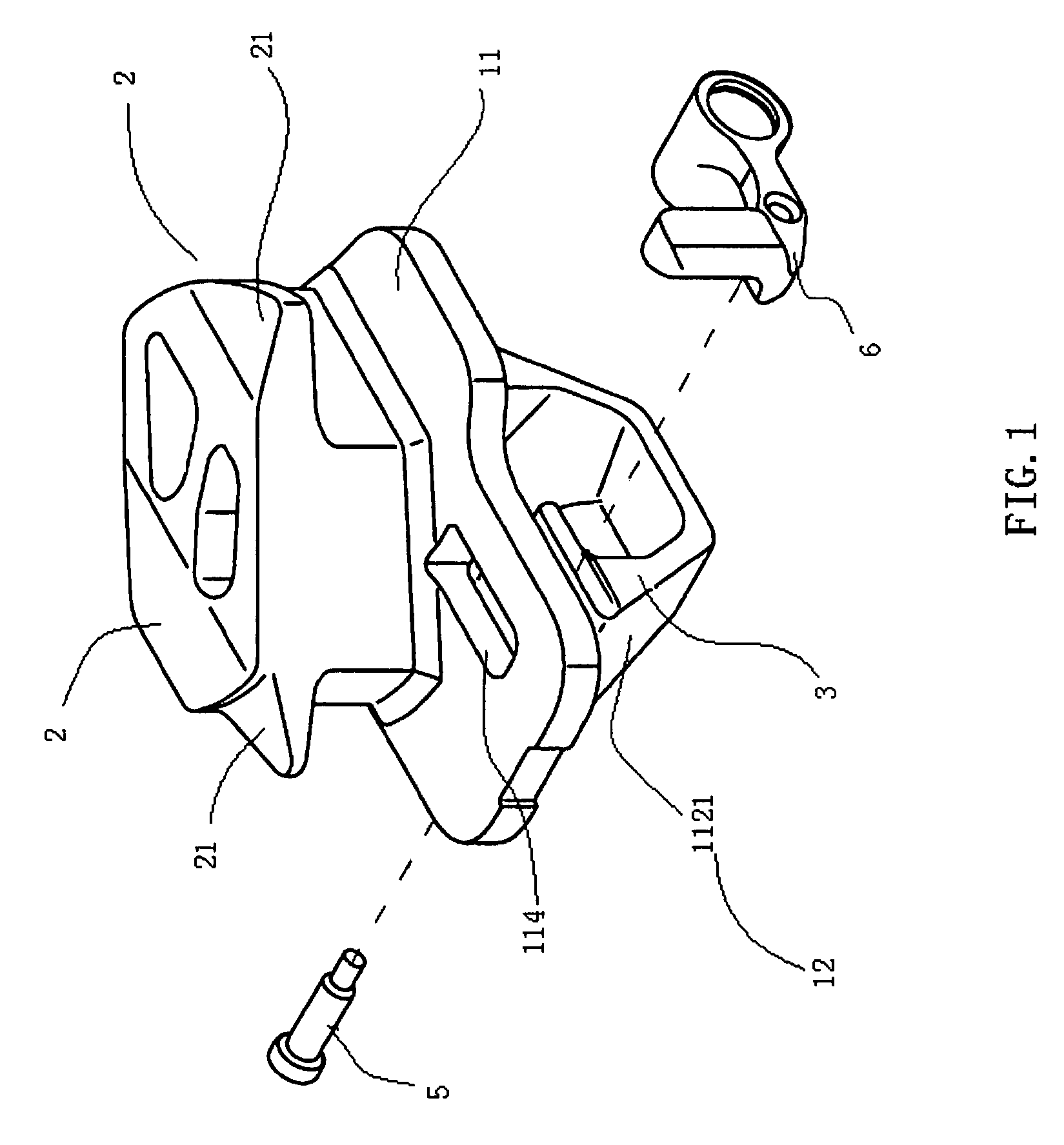
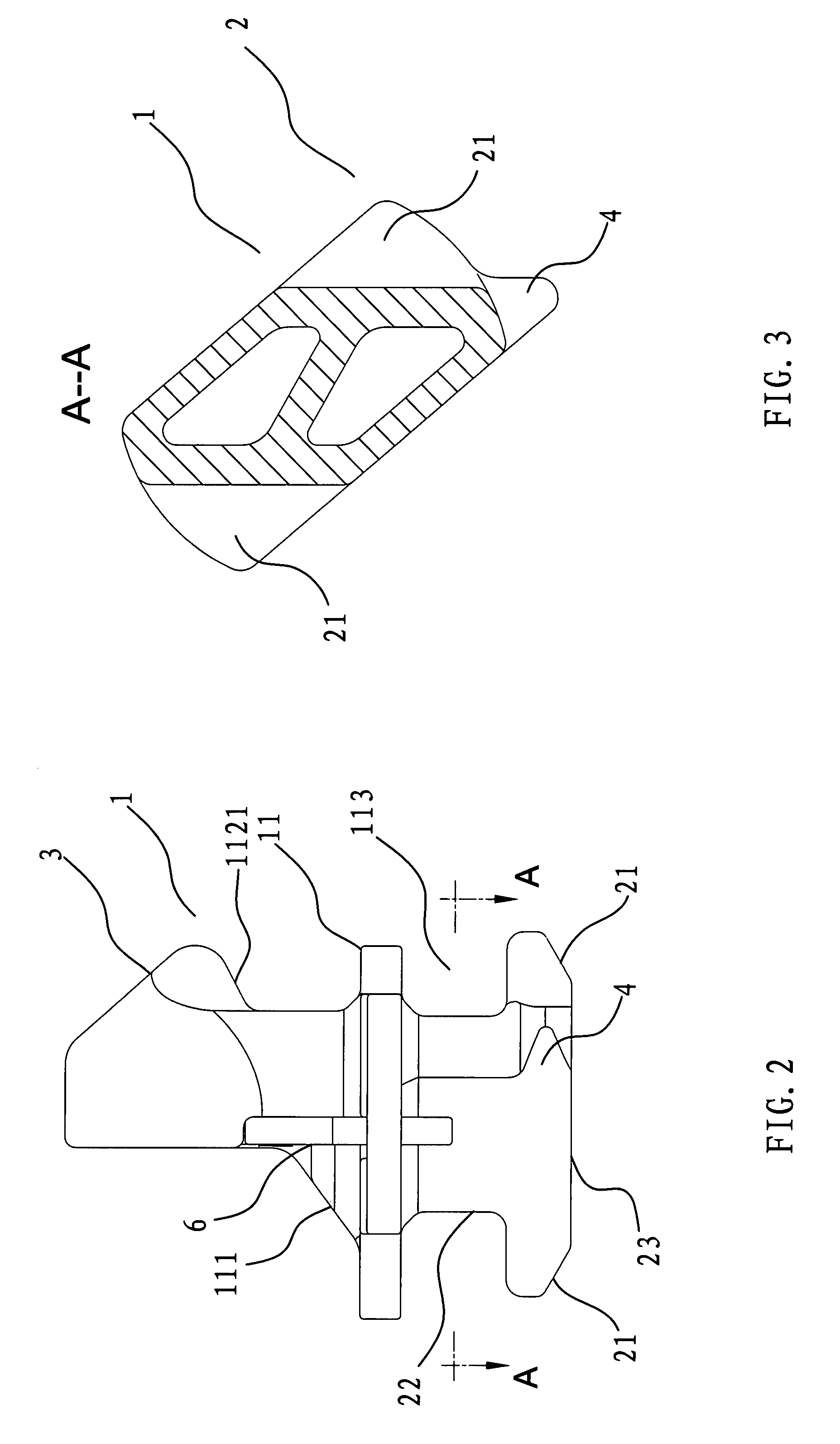
[0031]Referring to FIG. 1 of the drawings, an automatic container coupling tool 1 according to a preferred embodiment of the present invention is illustrated. The automatic container coupling tool is adapted for disposing between a pair of shipping containers, namely a lower container and an upper container, stacked one another for prevent a displacement between such two containers. Notably, the containers are prepared with bottom and top corner fitting housings with international standard, and each of the corner fitting housings is defined to leaver an exposing rectangular opening.

[0032]According to the present invention, the coupling tool 1 comprises a coupling tool body having a coupling platform 11, a bottom engager 2 downwardly extended from the platform 11 and adapted to be inserted into a top corner fitting housing of the lower container, wherein the bottom engager 2 comprises an engager neck 22 and an pair of opposed projecting lugs 21 sidewardly provided a lower edge of the...


PUM


Abstract

An automatic container coupling tool is disclosed, such coupling tool includes a coupling platform, a bottom engager and a top guiding protrusion oppositely extended from the coupling platform, the bottom engager has an engager neck, a pair of projecting lug extended from the engager neck to form a pair of holding cavity between the coupling platform and the projecting lugs, once the bottom engager is inserted into a corner fitting housing of a lower container, the bottom engager is rotated allowing the ceiling wall inserted into the holding cavity. The top guiding protrusion has a front guiding slope and a rear retaining shoulder, such that after the bottom engager is interlocked with the lower container, an upper container is perched onto the coupling tool, the opening edge of the bottom corner housing of the upper container will bias against the front guiding slop thus rearwardly shift the top guiding protrusion to snap onto the corner housing so as to couple the upper container onto the coupling tool as well.

Description

BACKGROUND OF THE PRESENT INVENTION[0001]1. Field of Invention[0002]The present invention relates to a kind of coupling tool, and more particularly, relates to a kind of automatic shipping container coupling tool which is simple in structure, convenient and reliable in practices for detachably stacking shipping containers.[0003]2. Description of Related Arts[0004]Commonly, the shipping containers are stacked one another for achieving an optimized efficiency in transportation. To ensure the security, one or more couplers would be applied between any pair of overlaid containers. On the other hand, shipping containers are designed to fit standard size, and are prepared with corner fittings with international standard size. Each of such corner fittings has an exposed opening defined thereon for insertion of the couplings.[0005]A coupling, or a coupler, is a mechanism for vertically connecting shipping containers during transportation. The design of such couplers is very important, since...

Claims


Application Information

Patent Timeline
Patent Type & Authority Patents(United States)
IPC IPC(8): A44B1/04
CPCB60P7/132B65D90/0013Y10T24/28
Inventor DING, YINQING
Owner KUSN LUCKY SEA IND
Learn More