
Storage bank for ions

a technology of storage bank and ions, which is applied in the direction of mass spectrometer, stability-of-path spectrometer, separation process, etc., can solve the problems of not being able to store identical fractions of ions, not having commercially available mass spectrometers which can record and deliver a hundred or more spectra, and accumulating ions

Active Publication Date: 2010-05-18
BRUKER DALTONIK GMBH & CO KG
View PDF22 Cites 49 Cited by
  • Summary
  • Abstract
  • Description
  • Claims
  • Application Information

AI Technical Summary

Benefits of technology

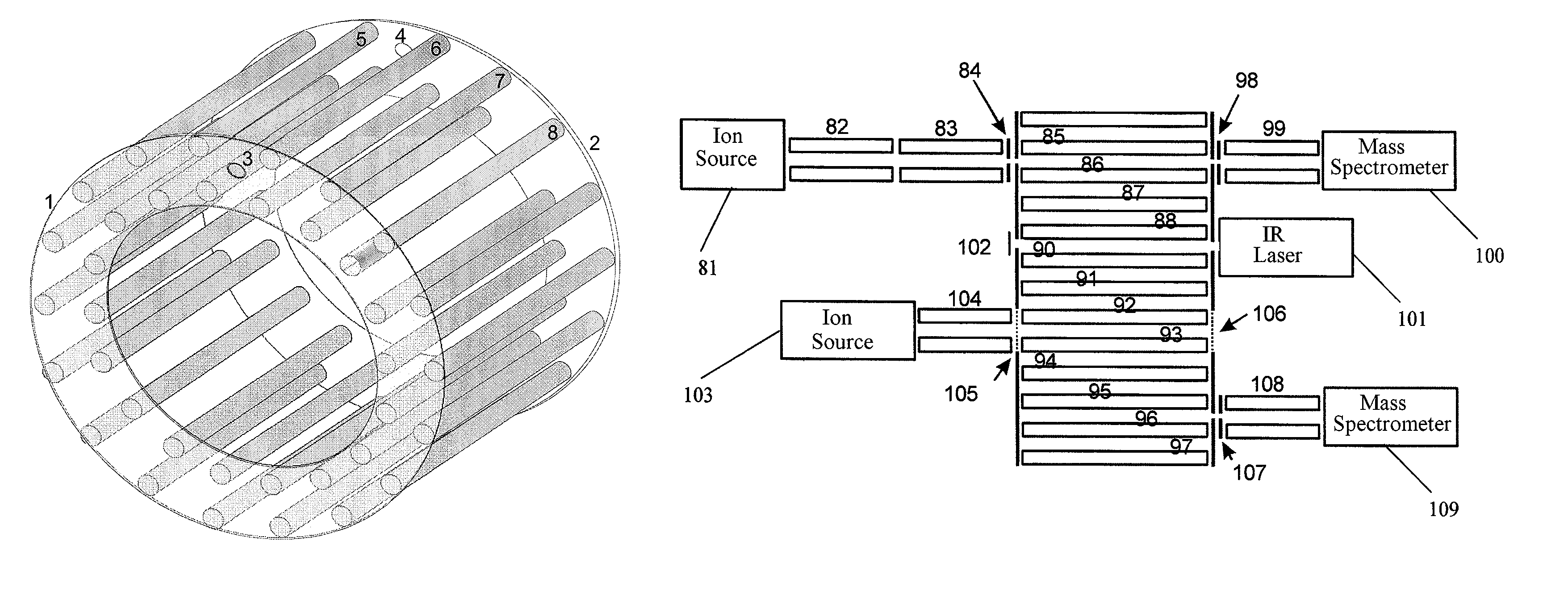
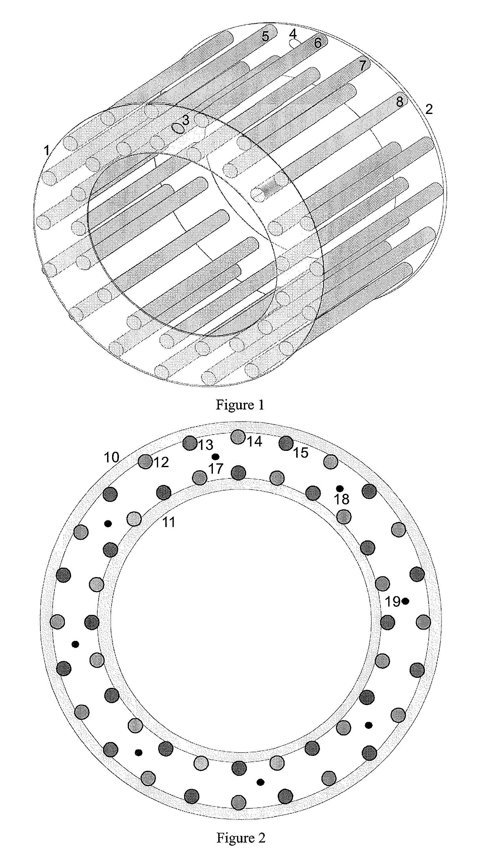
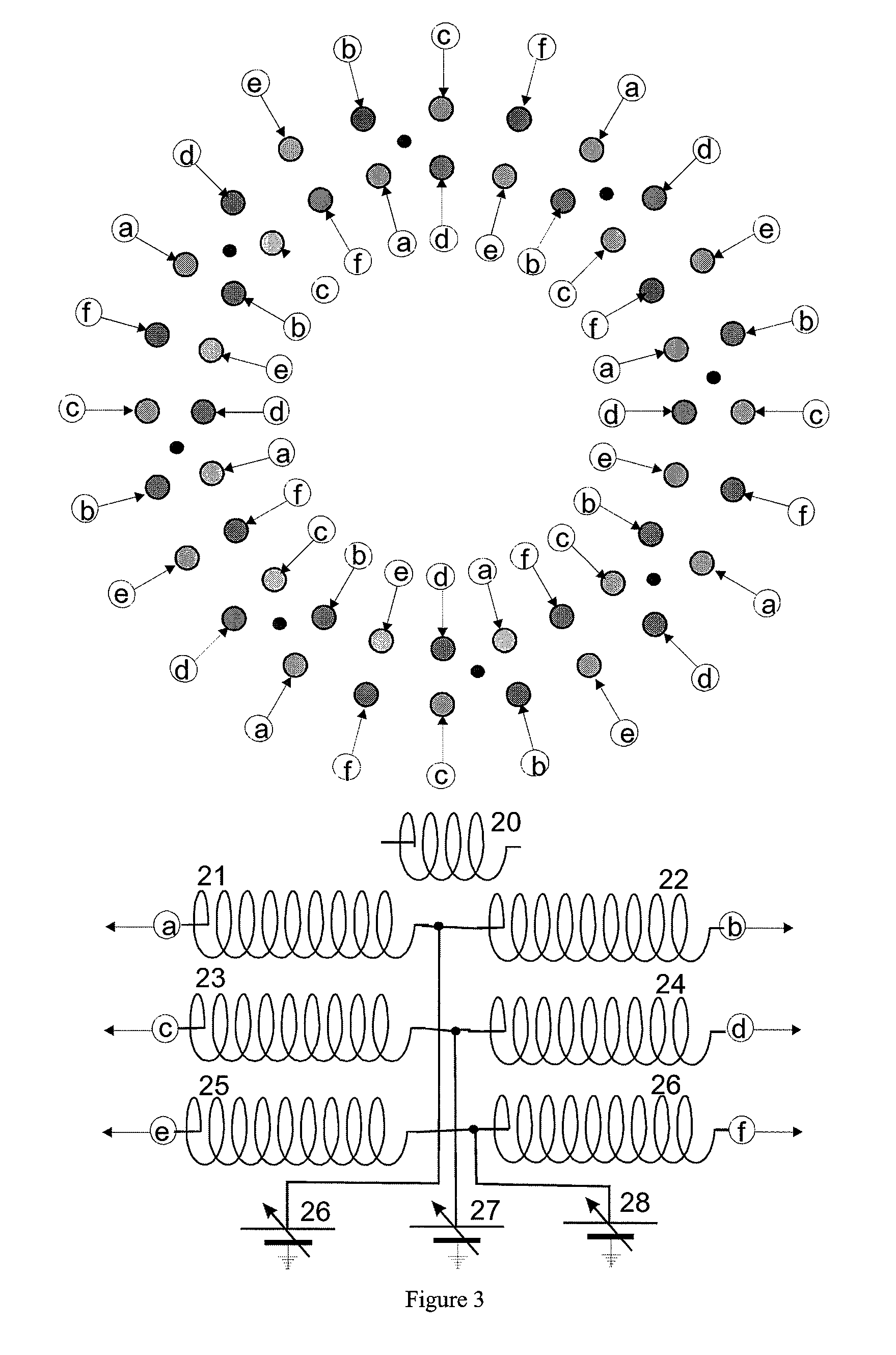
The present invention is a storage bank with parallel storage cells, each taking the form of an RF multipole rod system. The cells can be filled with damping gas at a pressure of between about 10−2 and 10+3 Pascal. The RF voltages for the pole rods and the DC pulses for the individual pairs of pole rods can be supplied by a power supply. The storage cells can be lined up in a single plane or as an open or closed chain of parallel cells on a virtual cylindrical surface. The multipole rod systems of the storage cells are equipped with terminating electrodes at both ends. The receiving storage cells can be filled from the ion guide with ions of an ion current profile. The storage bank may include at least one delivering storage cell for feeding ions to different analyzers. The storage cells are filled with damping gas to thermalize the ions and collect them close to the axis. The storage bank can be used for various purposes such as accumulative collection of ions, division up of ions, and subjecting them to different processes.

Problems solved by technology

There are, as yet, no commercially available mass spectrometers which can record and deliver a hundred or more spectra per second.
The storage bank disclosed in U.S. Pat. No. 5,811,800 cannot accumulate ions, however.
It cannot store identical fractions of ions from consecutive separation runs in the same storage cells because the storage cells arranged in series can only be filled from the preceding storage cell, and thus do not permit a second filling with ions from the same type of fraction from a subsequent separation run.
This time resolution is several orders of magnitude higher than the time resolution required for the separation methods used here, and so does not represent a solution to the problem.

Method used


Image

  • Storage bank for ions
  • Storage bank for ions
  • Storage bank for ions

Examples


Embodiment Construction

[0033]Ions may be transferred ion-optically from a feed with good focusing properties into ion storage devices with any configuration, as shown schematically in FIG. 7. However, a well-focusing feed in an RF ion guide requires a damping gas inside the ion guide and the ion-optical transfer requires a collision-free region (i.e., a good high vacuum). The ion storage devices, on the other hand, require a damping gas to operate without losses. This type of transfer presents a vacuum problem that can be solved by pumps with extremely high evacuation power. Even then, the transitions between the spaces at different pressure, which require very small apertures, create ion-optical problems. This type of storage bank must therefore be rejected because of the vacuum problems. A solution must be found which transfers the ions from the feeding ion guide into the storage cells without changing the prevailing gas pressures.

[0034]It would also be possible, in principle, to arrange parallel storag...


PUM


Abstract

The invention relates to instruments for storing ions in more than one ion storage device and to the use of the storage bank thus created. The ion storage bank includes several storage cells configured as RF multipole rod systems, where the cells contain damping gas and are arranged in parallel. Each pair of pole rods is used jointly by two immediately adjacent storage cells such that the ions collected can be transported from one storage cell to the next by briefly applying DC or AC voltages to individual pairs of pole rods. The ions can thus be transported to storage cells in which they are fragmented or reactively modified, or from which they can be fed to other spectrometers. In particular, a circular arrangement of the storage cells on a virtual cylindrical surface makes it possible to accumulatively fill the storage cells with ions of specific fractions from temporally sequenced separation runs.

Description

PRIORITY INFORMATION[0001]This patent application claims priority from German patent application 10 2006 040 000.3 filed Aug. 25, 2006, which is hereby incorporated by reference.FIELD OF THE INVENTION[0002]The invention relates to devices for storing ions in more than one ion storage volume and to the use of the storage bank thus created.BACKGROUND OF THE INVENTION[0003]Most mass spectrometers in use today basically operate discontinuously; they deliver mass spectra at rates which nowadays are generally between one and a maximum of twenty mass spectra per second. If daughter or granddaughter ion spectra are measured, the scan rate sinks considerably. There are, as yet, no commercially available mass spectrometers which can record and deliver a hundred or more spectra per second. Time-of-flight mass spectrometers with orthogonal ion injection can operate with 5,000 to 15,000 individual spectra per second, which are digitized in transient recorders and added in real time; but, for rea...

Claims


Application Information

Patent Timeline
Patent Type & Authority Patents(United States)
IPC IPC(8): H01J49/42
CPCH01J49/4225H01J49/063H01J49/4295
Inventor FRANZEN, JOCHENBAYKUT, GOKHAN
Owner BRUKER DALTONIK GMBH & CO KG
Learn More