
Channel equalizer and digital television receiver using the same

a technology of channel equalizer and digital television receiver, which is applied in the direction of digital transmission, television system details, and baseband system details, etc., can solve the problems of deterioration of time domain equalizer performance, frequent decision errors, and very serious signal distortion, and achieve constant equalization performance and robust reception performance.

Active Publication Date: 2010-05-11
LG ELECTRONICS INC
View PDF2 Cites 8 Cited by
  • Summary
  • Abstract
  • Description
  • Claims
  • Application Information

AI Technical Summary

Benefits of technology

[0012]An object of the present invention is to provide a channel equalizer and a digital television receiver using the same, in which the affection of channel estimation value is minimized when a channel is equalized in frequency domain so that the channel equalizer and the digital television receiver has constant equalization performance even in case an estimation channel error exists or in the dynamic channel situation that changes faster than appearance frequency of a training signal.
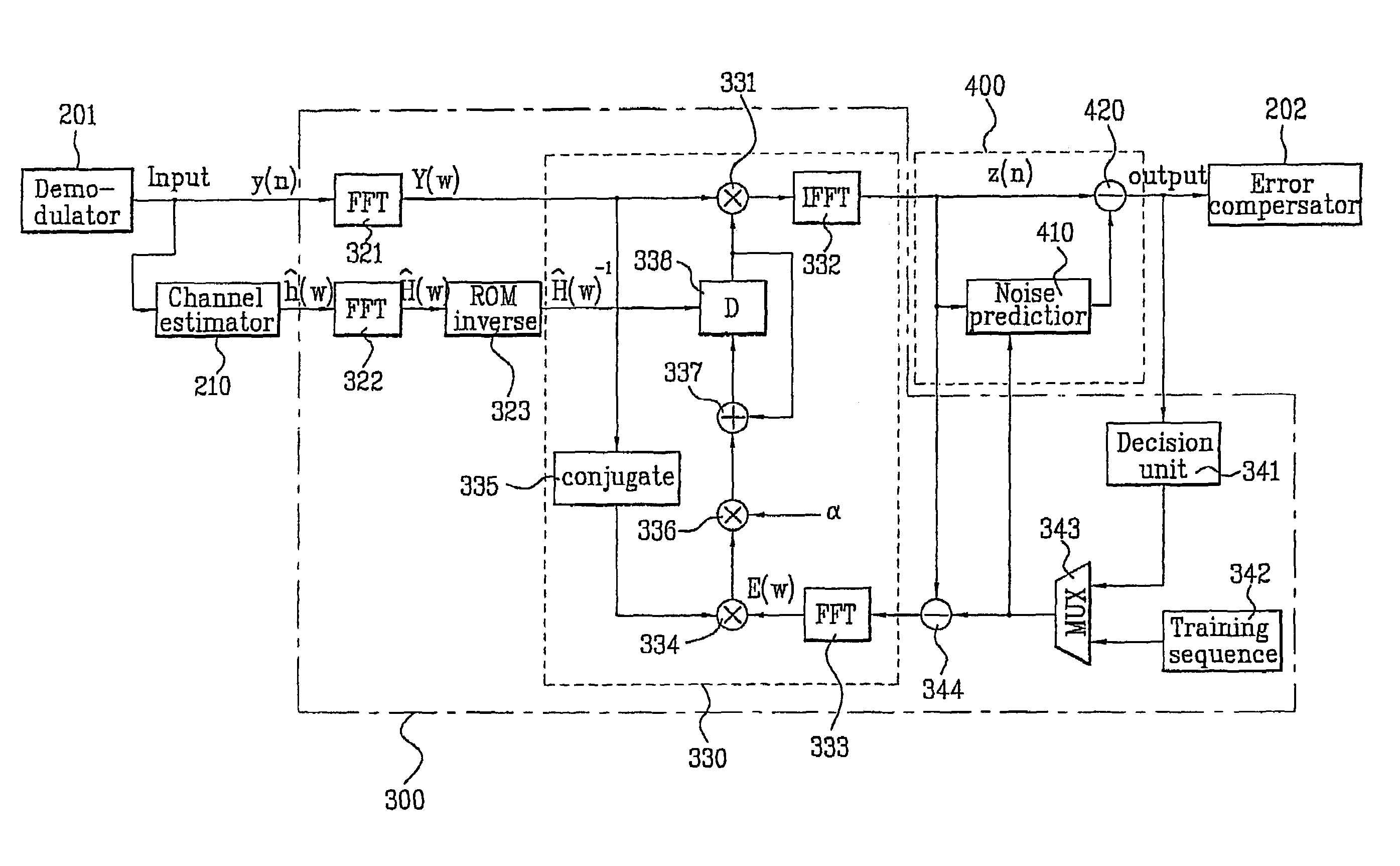
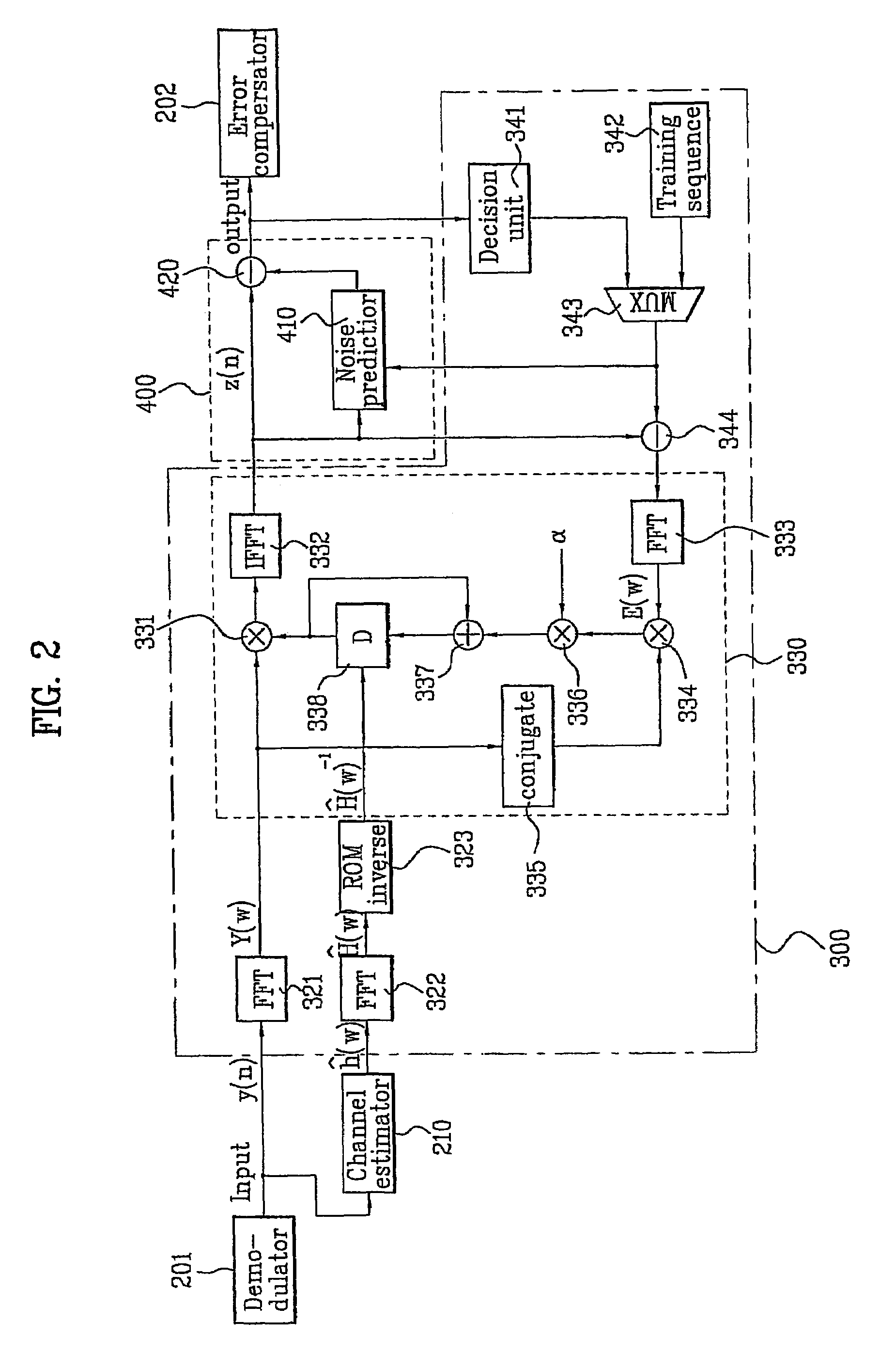
[0033]In another aspect of the present invention, a digital television receiver comprises: a demodulator for digitalizing a received signal demodulating the digitalized signal into a base band signal; a channel estimator for estimating an impulse response of a transmission channel from an output signal of the demodulator; a channel distortion compensator for converting the received base band signal and the impulse response of the estimated transmission channel into frequency domain signals, setting a reciprocal of the impulse response of the estimated transmission channel in a frequency domain as an initial coefficient, receiving channel equalized data fed back in data duration, updating the coefficients continuously, compensating distortion of the received signal converted into the frequency domain, and converting the compensated received signal back into a time domain; a noise canceller for predicting a noise from an output of the channel distortion compensator, the noise being amplified when equalized, and eliminating the amplified noise contained in the time domain signal outputted from the channel distortion compensator; and an error compensator for compensating a phase and an error of data outputted from the noise canceller and outputting the compensated data for channel decoding.

Problems solved by technology

The signal transmitted to the receiver is interfered with adjacent signal during its passing through the transmission channel of multiple paths, so that the signal is distorted very seriously.
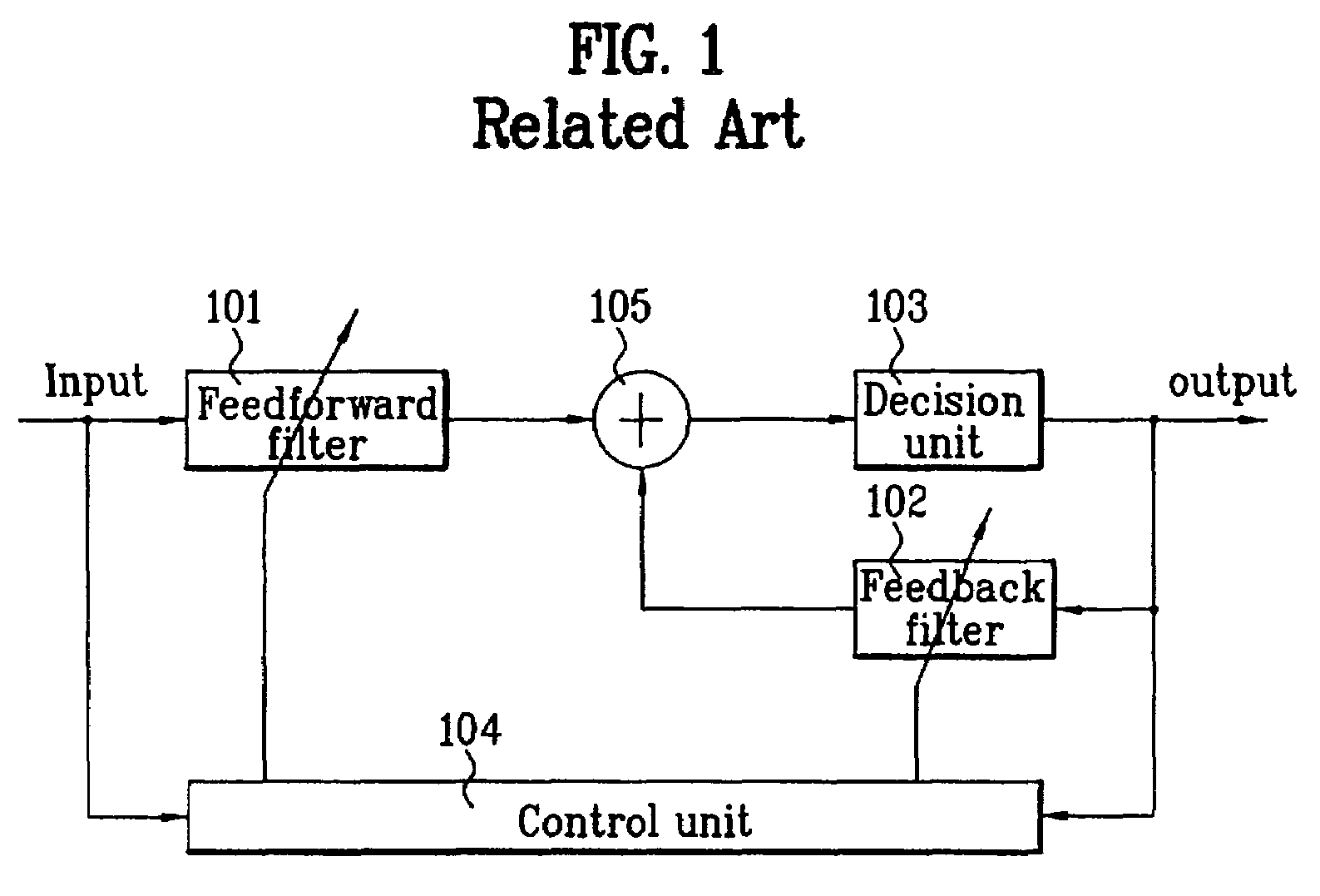
However, if channel distortion is too serious, the decision error occurs frequently on the decision value inputted to the feedback filter 102 and the wrong decision value is infinitively looped in the feedback filter 102.
So, the time domain equalizer can deteriorate in its performance.
In other words, in case the locations of a main path and a reflection path in the time domain equalizer are occasionally changed, the time domain equalizer deteriorates in performance and frame synchronization changes frequently so that channel decoding performed in a rear stage of the equalizer is impossible.
In this situation, it is meaningless to distinguish a main signal from reflection signals and the DFE cannot equalize the signals correctly so that the DFE is not proper to multiple path and SFN channel compensation.

Method used


Image

  • Channel equalizer and digital television receiver using the same
  • Channel equalizer and digital television receiver using the same
  • Channel equalizer and digital television receiver using the same

Examples


Embodiment Construction

[0042]Reference will now be made in detail to the preferred embodiments of the present invention, examples of which are illustrated in the accompanying drawings. Wherever possible, the same reference numbers will be used throughout the drawings to refer to the same or like parts.

[0043]FIG. 2 is a block diagram illustrating the entire configuration of a channel equalizer of a digital television receiver according to the present invention. A channel equalizer comprises a channel estimator 210, a channel distortion compensator 300 and a noise canceller 400. The channel estimator 210 estimates a transmission channel in a time domain by using a training signal. A channel distortion compensator 300 converts the estimated transmission channel into a frequency domain, uses the frequency response of the inverse channel of the estimated transmission channel (converted) into the frequency domain as an initial coefficient for frequency domain equalization, adaptively equalize the channel-distor...


PUM


Abstract

Disclosed are a channel equalizer and digital television receiver using the same. The equalizer comprises a channel estimator, a channel distortion compensator and noise canceller. The channel estimator estimates an impulse response of a transmission channel from a received signal. The channel distortion compensator transforms and processes the received signal and the estimated impulse response. The noise canceller predicts and eliminates amplified noise generated during equalization.

Description

CROSS-REFERENCE TO RELATED APPLICATIONS[0001]This application claims the benefit of the Korean Application No. P2002-79963 filed on Dec. 14, 2002, which is hereby incorporated by reference.BACKGROUND OF THE INVENTION[0002]1. Field of the Invention[0003]The present invention relates to a channel equalizer used in a frequency domain and a digital television receiver using the same.[0004]2. Discussion of the Related Art[0005]In a general digital communication system, a transmitter maps digital information such as voice, data and image onto symbols, converts each symbol into an analog signal proportional to an amplitude or a phase corresponding to the symbol, and transmits the analog signal to a receiver through a transmission channel. The signal transmitted to the receiver is interfered with adjacent signal during its passing through the transmission channel of multiple paths, so that the signal is distorted very seriously. In order to restore the original signal from a distorted signa...

Claims


Application Information

Patent Timeline
Patent Type & Authority Patents(United States)
IPC IPC(8): H04N5/21H04L25/03H04N7/015
CPCH04N5/211H04N5/21H04L2025/0349H04N7/015
Inventor KIM, JOON TAEHONG, SUNG RYONGCHOI, IN HWANKANG, KYUNG WONSHIN, JONG WOONGKIM, BYOUNG GILLKIM, WOO CHANKIM, JAE HYOUNG
Owner LG ELECTRONICS INC
Learn More