
Wall-mounted electrical device with modular antenna bezel frame

a technology of electrical control device and antenna bezel frame, which is applied in the direction of antenna equipment with additional functions, lighting apparatus, electric lighting sources, etc., can solve the problem of not being practical to use behind a metal-faced facepla

Active Publication Date: 2010-05-11
CRESTRON ELECTRONICS
View PDF32 Cites 86 Cited by
  • Summary
  • Abstract
  • Description
  • Claims
  • Application Information

AI Technical Summary

Benefits of technology

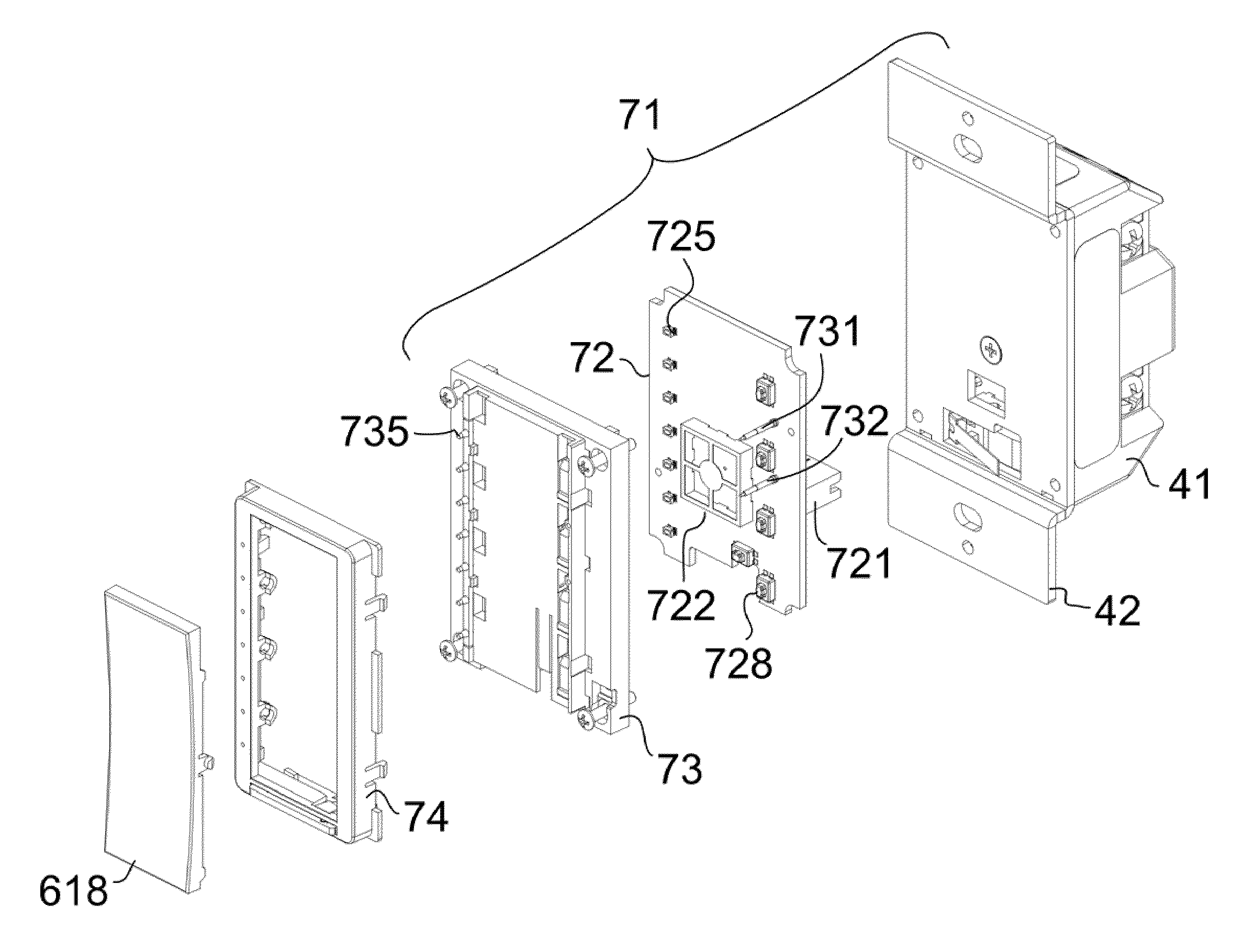
[0009]An illustrative electrical device configured to install within a wall mounted electrical box includes an antenna bezel frame, an antenna element, and a radio frequency circuitry component. At least a portion of the antenna bezel frame is configured to protrude through an opening in a faceplate. The antenna element is mounted to the antenna bezel frame such that the antenna element is located a distance forward of a plane that contains a front surface of the faceplate when the field configurable electrical device is installed. The radio frequency circuitry component is in electrical communication with the antenna element and is configured to receive a control signal from the antenna element.

Problems solved by technology

Such a solution is not practical for use behind a metal-faced faceplate, such as those typically found in residential kitchens and bathrooms, commercial buildings, etc.

Method used


Image

  • Wall-mounted electrical device with modular antenna bezel frame
  • Wall-mounted electrical device with modular antenna bezel frame
  • Wall-mounted electrical device with modular antenna bezel frame

Examples


Embodiment Construction

[0064]Reference will now be made to the illustrative embodiments depicted in the drawings, and specific language will be used herein to describe the same. It will nevertheless be understood that no limitation of the scope of the subject matter described herein is thereby intended. Alterations and further modifications of the embodiments illustrated and described herein, and additional applications of the embodiments illustrated and described herein, which would occur to one skilled in the relevant art and having possession of this disclosure, are to be considered within the scope of the subject matter described herein. Unless the context clearly requires otherwise, throughout the description and the claims, the words ‘comprise’, ‘comprising’, and the like are to be construed in an inclusive sense as opposed to an exclusive or exhaustive sense; that is to say, in the sense of “including, but not limited to”.

[0065]In the last several years, wireless infrastructure has developed at a r...


PUM


Abstract

An electrical device configured to install within a wall mounted electrical box includes an antenna bezel frame, an antenna element, and a radio frequency circuitry component. At least a portion of the antenna bezel frame is configured to protrude through an opening in a faceplate. The antenna element is mounted to the antenna bezel frame such that the antenna element is located a distance forward of a plane that contains a front surface of the faceplate when the field configurable electrical device is installed. The radio frequency circuitry component is in electrical communication with the antenna element and is configured to receive a control signal from the antenna element.

Description

BACKGROUND[0001]1. Technical Field[0002]The subject matter described herein relates to wall mounted electrical control devices that can be remotely controlled and monitored via radio frequency transmissions. The subject matter described herein also relates to remote control devices for controlling and monitoring the wall mounted electrical control devices. More particularly, the subject matter described herein relates to electrical devices that can include one or more interchangeable key capsules, one or more associated interchangeable bezel frames which include a radio frequency antenna element, and one or more interchangeable radio frequency circuitry components.[0003]2. Background Art[0004]The field of home automation is rapidly developing. The ability to control electrical fixtures, appliances, and electronics remotely or through a central location is becoming more and more common place. Remote electronic control devices, such as lighting dimmers, include control circuitry and p...

Claims


Application Information

Patent Timeline
Patent Type & Authority Patents(United States)
IPC IPC(8): H01Q1/24
CPCH01Q1/007H05B37/0272H01Q1/44H01Q1/22H05B47/19
Inventor FELDSTEIN, GEORGEWISNIEWSKI, STANBELLINGHAM, PHILIPDRAGANOVIC, KRUNOSLAV
Owner CRESTRON ELECTRONICS
Learn More