
Method and apparatus for driving printer head and image formation

a technology of printer head and printer head, which is applied in the direction of printing and other printing apparatus, can solve the problems of large increase in power consumed to print an image and inability to reduce the size of image forming equipment, and achieve the effect of low power without reducing printing quality or speed

Inactive Publication Date: 2010-05-04
S PRINTING SOLUTION CO LTD
View PDF14 Cites 0 Cited by
  • Summary
  • Abstract
  • Description
  • Claims
  • Application Information

AI Technical Summary

Benefits of technology

"The present invention provides a method and apparatus for driving a printer head to print an image with low power without reducing printing quality or speed. The printer head is driven using an analysis of printing power consumption before printing occurs. The method involves dividing the printing elements into N driving groups and calculating the number of driving groups based on the distance between adjacent printing elements. The number of driving groups is increased if the calculated print lines are at least a certain number. The printing elements convey ink onto a medium to print an image. The apparatus includes a printer head, a data input unit, and a control unit for sequentially driving the printing elements. The control unit calculates the number of driving groups based on the input image data and increases the number of driving groups if the calculated print lines are at least a certain number. The method and apparatus can be implemented in a computer-readable medium."

Problems solved by technology

Therefore, in the case of image forming equipment having an array-head structure, such as inkjet printers, power consumed to print an image greatly increases as the number of printing heads increase.
Consequently, the size of the image forming equipment cannot be reduced due to the physical size of high-power power supplies.

Method used


Image

  • Method and apparatus for driving printer head and image formation
  • Method and apparatus for driving printer head and image formation
  • Method and apparatus for driving printer head and image formation

Examples


Embodiment Construction

[0025]The present invention will now be described more fully with reference to the accompanying drawings, in which exemplary embodiments of the invention are shown.

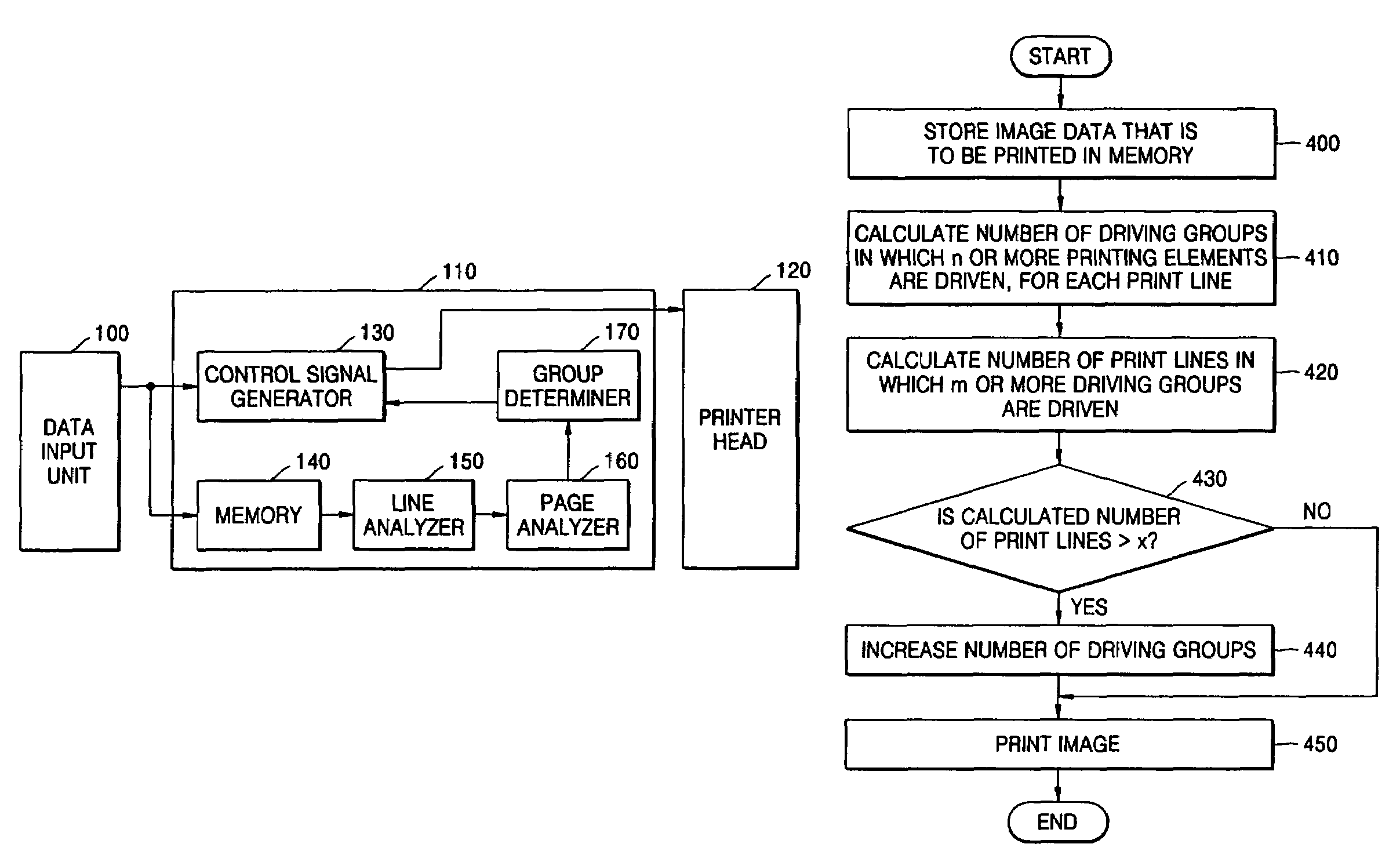
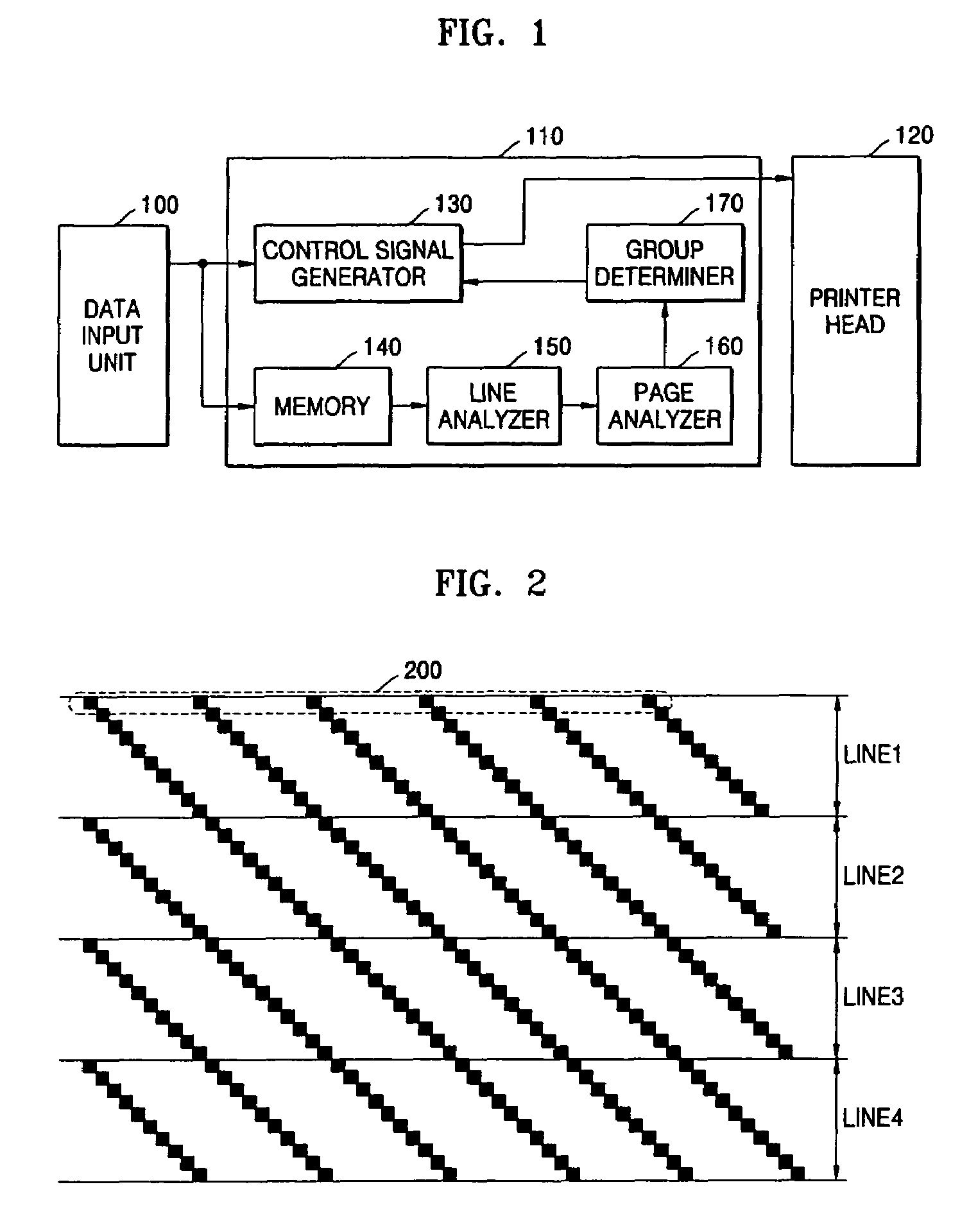
[0026]FIG. 1 illustrates a block diagram of an image forming apparatus according to an embodiment of the present invention. The image forming apparatus includes a data input unit 100, a control unit 110, and a printer head 120. The control unit 110 includes a control signal generator 130, a memory 140, a line analyzer 150, a page analyzer 160, and a group determiner 170.

[0027]The data input unit 100 receives image data to be printed from a source such as a personal computer (PC), a digital camera, or a personal digital assistant (PDA).

[0028]The control unit 110 generates control signals to control operation of printer head 120 according to the input image data obtained from data input unit 100. Printer head 120 receives control signals from control unit 110 and drives a plurality of printing elements to print an image. Pr...


PUM


Abstract

Provided are a method and apparatus for driving printing elements of a printer head in an image forming apparatus. The method includes calculating a number of driving groups among multiple driving groups in which at least a first predetermined number of printing elements are driven for each print line. The method calculates a number of print lines wherein the calculated number of driving groups are not less than a second predetermined number. The number of driving groups are increased if the calculated print lines is not less than a third predetermined number. Thus, it is possible to print with less power without a reduction in print quality or speed by controlling the driving of the printer head. In addition, the overall size of the image forming apparatus can be reduced by using low-power power supply.

Description

[0001]This application claims the benefit of priority under 35 U.S.C. § 119(a) of Korean Patent Application No. 10-2004-0113700, filed on Dec. 28, 2004 in the Korean Intellectual Property Office, the entire disclosure of which is hereby incorporated by reference.BACKGROUND OF THE INVENTION[0002]1. Field of the Invention[0003]The present invention relates to an image forming method and apparatus. More particularly, the present invention relates to a method and apparatus for driving printing elements of a printer head by analyzing the power necessary to print a page before printing, and driving the printing elements according to the analysis results.[0004]2. Description of the Related Art[0005]Generally, image forming equipment convert a document written by a user via an application program, or an image photographed with, for instance, a digital camera, into encoded data. The image forming equipment outputs the encoded data onto media, thereby making the document or image visible to t...

Claims


Application Information

Patent Timeline
Patent Type & Authority Patents(United States)
IPC IPC(8): B41J2/15
CPCB41J2/0452B41J2/04586B41J2/04545B41J29/38
Inventor JEONG, JIN-WOOK
Owner S PRINTING SOLUTION CO LTD
Learn More