Pressure control device

a control device and pressure control technology, applied in the direction of functional valve types, liquid dispensing, domestic objects, etc., can solve the problems of less container pressure, pressure in the first and second chambers, and pressure in the pressure control device, and achieve the effect of reducing the total usable space in the bottle and facilitating implementation

Active Publication Date: 2010-05-04
INTELLIGENT PACKAGING SYST GROUP +1
View PDF13 Cites 23 Cited by
  • Summary
  • Abstract
  • Description
  • Claims
  • Application Information

AI Technical Summary

Benefits of technology

[0009]A main advantage of the present invention is that the pressure control device can be pressurized after implementation and filling of the liquid dispensing bottle. Since the second chamber is encompassing the first chamber, a very compact pressure control device will be obtained so that the total usable space in the bottle is much larger as in known embodiments. As the pressure control device can be fabricated in advance and can be implemented easily in existing plastic bottles, the existing production and filling procedures for e.g. cosmetic products can be maintained with only little additional arrangements in the production line.
[0010]Further advantages of the invention are disclosed in the dependent claims and in the following description in which an exemplified embodiment of the invention is described with respect to the accompanying drawings.

Problems solved by technology

However, the design of the pressure control device is disadvantageous because of its large dimensions so that less of the container can be used for dispensing fluid.
A further important problem of the above described pressure control devices as a separate module is that the first and second chambers have to be pressurized before mounting in a container.
This in practice may be very difficult and costly to achieve e.g. in aluminium aerosol cans where the construction is in one-piece and the production lines run at very high outputs.
A further major disadvantage is that it has been shown that the pressure in a separate pressure control device which will be mounted afterwards in a container drops to a large extent during a period of some months which is necessary for storage and distribution in the commercial supply chain.
Thus the known pressure control devices are not suitable for application in a large industrial scale.

Method used


Image

  • Pressure control device
  • Pressure control device
  • Pressure control device

Examples


Embodiment Construction

[0021]Specific numbers dedicated to elements defined with respect to a particular figure will be used consistently in all figures if not mentioned otherwise.

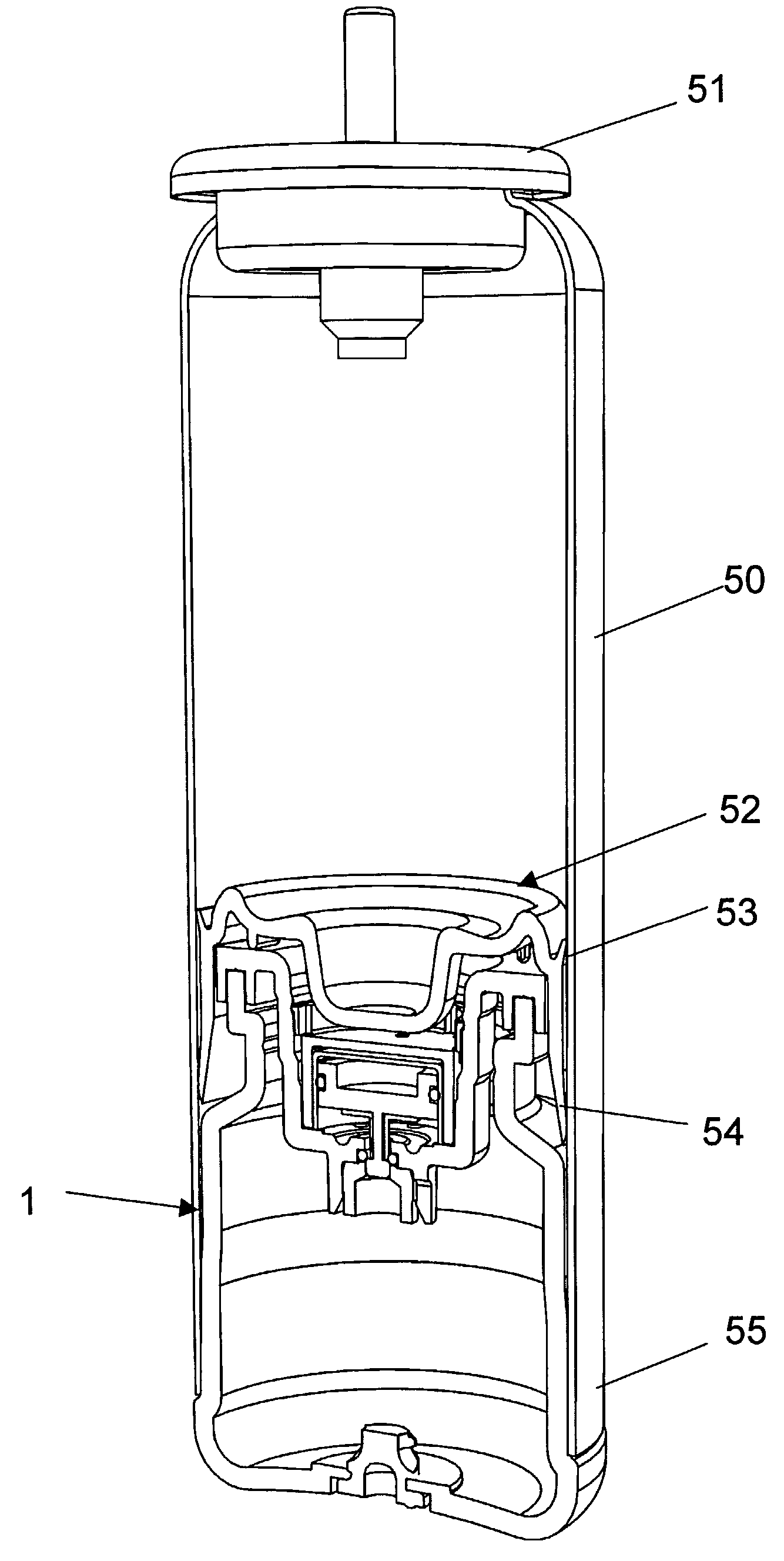
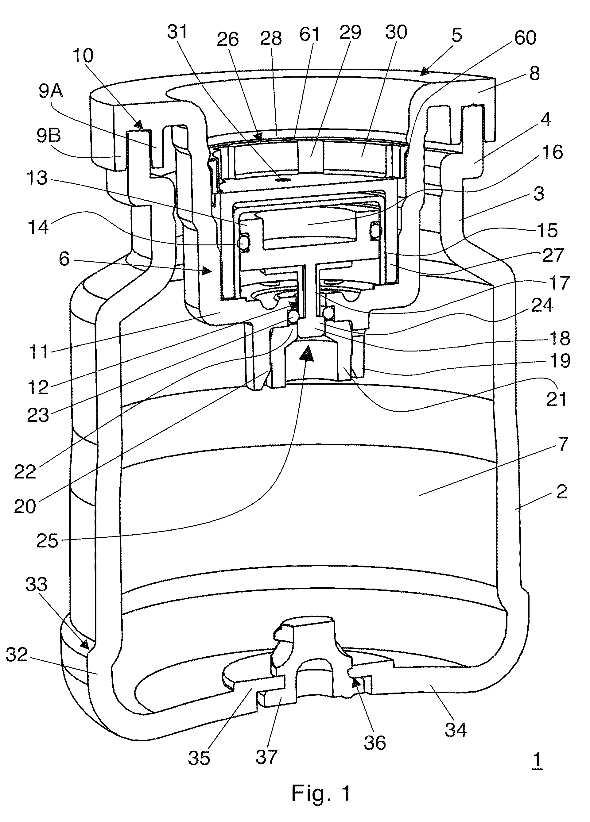
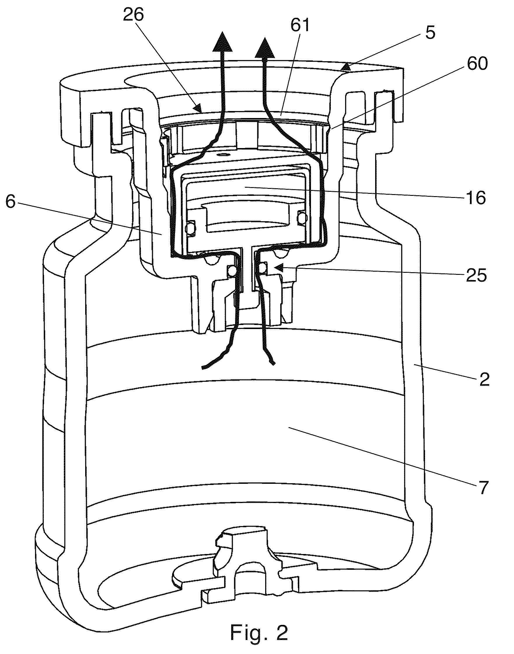
[0022]In FIGS. 1 and 2 a pressure control device 1 for maintaining a constant predetermined excess pressure in a container is shown in cross-section and in a perspective view. The device 1 consists of a substantially cylindrical container 2 with a tapered neck portion 3 and a flange 4, on which a ring-shaped insert or closure 5 having a steplike funnel 6 is mounted. The cylinder 2—indicated as “the second cylinder” in the claims—forms a second chamber 7 of the pressure control device 1. The outer rim 8 of the insert 5 has an outer downwardly directed ring part 9A and an inner downwardly directed ring part 9B, which ring parts include a groove 10. The insert 5 is mounted to the flange 4 of the cylinder 2 by ultrasonic welding. For that reason the inner surface of the groove 10 of the insert 5 has a saw-tooth or fluted structure u...


PUM

PropertyMeasurementUnit
pressureaaaaaaaaaa
pressureaaaaaaaaaa
volumeaaaaaaaaaa

Abstract

The invention is a pressurized gas providing and gas pressure regulating device. The invention is a container with an over pressurized second chamber of pressurized gas that can be released to the exterior of the container when a valve that is integrally connected to a piston that along with a first cylinder forms a first chamber that is filled with a comparably less over pressurized gas that pushes the valve open when the gas pressure outside of the container is too low, thereby permitting the over pressurized second chamber to fluidly connect via the valve and thereby increase the pressure outside the container, such as to a volume of gas located below a piston within a fluid dispenser, the first and second chambers are shaped as cylinders and the first cylinder fits within the second chamber.

Description

CROSS REFERENCE TO RELATED APPLICATIONS[0001]This application is entitled to the benefit of and incorporates by reference essential subject matter disclosed in International Patent Application No. PCT / IB2004 / 002522 filed on Aug. 5, 2004 and European Patent Application No. 04405059.9 filed Jan. 30, 2004.FIELD OF THE INVENTION[0002]The present invention concerns pressure control device for maintaining a constant predetermined excess pressure in a fluid dispensing container and a method for manufacturing such a pressure control device.BACKGROUND OF THE INVENTION[0003]PCT patent application WO-A-99 / 62791 discloses a fluid dispensing container with a pressure control device. The device described therein is provided for maintaining a constant predetermined pressure in a container which is arranged for dispensing a fluid. The pressure control device has a first chamber and a second chamber, as well as a closing member movable relative to the second chamber for releasing and closing a fluid...

Claims


Application Information

Patent Timeline
Patent Type & Authority Patents(United States)
IPC IPC(8): B67D7/60B65D83/14F16K17/06G05D16/10
CPCB65D83/64G05D16/10B65D83/663B29C65/08B29C65/1612B29C65/1635B29C65/1661B29C65/1683B29C65/48B29C66/1222B29C66/1224B29C66/542B29C66/5432B29C66/65B29C66/71B29C66/919B29C66/939B29L2031/7142B29K2067/003
Inventor REGAN, PHILIP MALCOLMVAN SWIETEN, ROY EDWIN
Owner INTELLIGENT PACKAGING SYST GROUP
Why Eureka
Try Eureka