
Electronically controlled brakes for walkers

a technology of electric control and brakes, applied in the direction of brake systems, mechanical devices, transportation and packaging, etc., can solve the problems of walking, as executed in the prior art, not being stable, and being difficult to lift, and achieve the effect of convenient operation

Inactive Publication Date: 2010-05-04
EINBINDER ELI
View PDF11 Cites 77 Cited by
  • Summary
  • Abstract
  • Description
  • Claims
  • Application Information

AI Technical Summary

Benefits of technology

Enhances user mobility by providing stable and controlled movement, adaptable to different user conditions, and easy operation, ensuring safety and convenience for users with varying strengths and abilities.

Problems solved by technology

Walkers, as executed in the prior art, have some problems, however.
A lightweight walker can be easy to lift, but because of its lightness, it may not be stable, whereas a heavy walker will be stable, but difficult to lift.
The operation of lifting and moving a conventional walker can make locomotion difficult, awkward, and unstable for people who are too weak to firmly grasp or to lift it, for during the time that the walker is being lifted and moved, the user is less stable even than would ordinarily be the case when standing alone and without external support.
Thus, the act of lifting the walker can be a source of difficulty for the user.
However, wheels make the walker essentially unstable.
Again, however, the use of hand brakes presents its own problems, since the operator may be afflicted with arthritis or some other debilitating injury or illness which prevents or makes difficult the laborious operation of the brakes and maintenance of the steady pressure required to operate them.
These hand brakes are also not well suited for one needing a steadying support after a sudden stumble, since at such times, when the user quickly reaches for the walker, he or she is unlikely to be able readily to grasp the hand brake, which may be far in front of the user, and may instead simply push the walker further away.
Further, squeezing a brake may be uncomfortable or difficult to coordinate with the users attempts to maintain stability.
Unfortunately, however, most of the “downward” force applied to a walker in motion is, in reality, a forward force.
Therefore, such arrangements can be hazardous to the operator, since they do not respond to users' needs at different times, and may not be responsive to the characteristics and abilities of a particular user, with the result that the walker can roll away from the operator if insufficient pressure is being applied, or may stop prematurely upon application of a light pressure.
Many walkers use a combination of wheels and ground-engaging legs; for example, two legs at the rear of the walker and two wheels at the front, to prevent accidental rolling, but such walkers can be awkward to use, since they require some lifting and rolling at the same time.
However, such devices may be heavy, and not only energy inefficient, but may be dangerous to disabled people.
Further, they may essentially remove control of operation from the operator and may, if accidentally activated, present additional danger to the operator.
A still further problem with prior walking aids is their inability to provide for differing and changing needs.
Individual's needs evolve as their conditions improve or deteriorate, but prior walkers have not been able to accommodate to such changes.
As a result, a walker that is initially suitable for an individual may gradually become unsuitable over a period of time, and may not be usable by another person, such as a friend or family member.
The electrically controlled brakes of the foregoing patents are an improvement over prior walkers with mechanically operated brakes, for as discussed above, mechanical brakes may be difficult to operate for those having reduced strength in their hands or who have slowed reflexes, and may be hard to grip for operators having arthritis in their hands.
Further, mechanical brakes are not a realistic option for those having severe impairment of the hands, or who may be missing a hand.
Additionally, the prior walkers, whether having mechanical or electrical brakes, can be unstable when the operator tries to move from a sitting to a standing position, and can be hard to push when used on uphill inclines and may roll away from the user when used on downhill inclines.

Method used


Image

  • Electronically controlled brakes for walkers
  • Electronically controlled brakes for walkers
  • Electronically controlled brakes for walkers

Examples


Embodiment Construction

[0031]Walkers and other devices for assisting individuals who are infirm, or who have medical conditions that limit their mobility, have been available for many years, and have been of great help to large numbers of people. Such devices are commercially available in a variety of configurations to provide easily maneuverable walkers wheel chairs and the like. As discussed above, the present invention is described in conjunction with walkers, but may be adapted to other motion assisting devices, as well. As described in the afore-mentioned U.S. Pat. Nos. 5,636,651 and 5,794,639, walkers may be provided with both mechanical and electrically operated brakes to assist in controlling their movement. The present invention is directed to improvements in control systems for such devices.

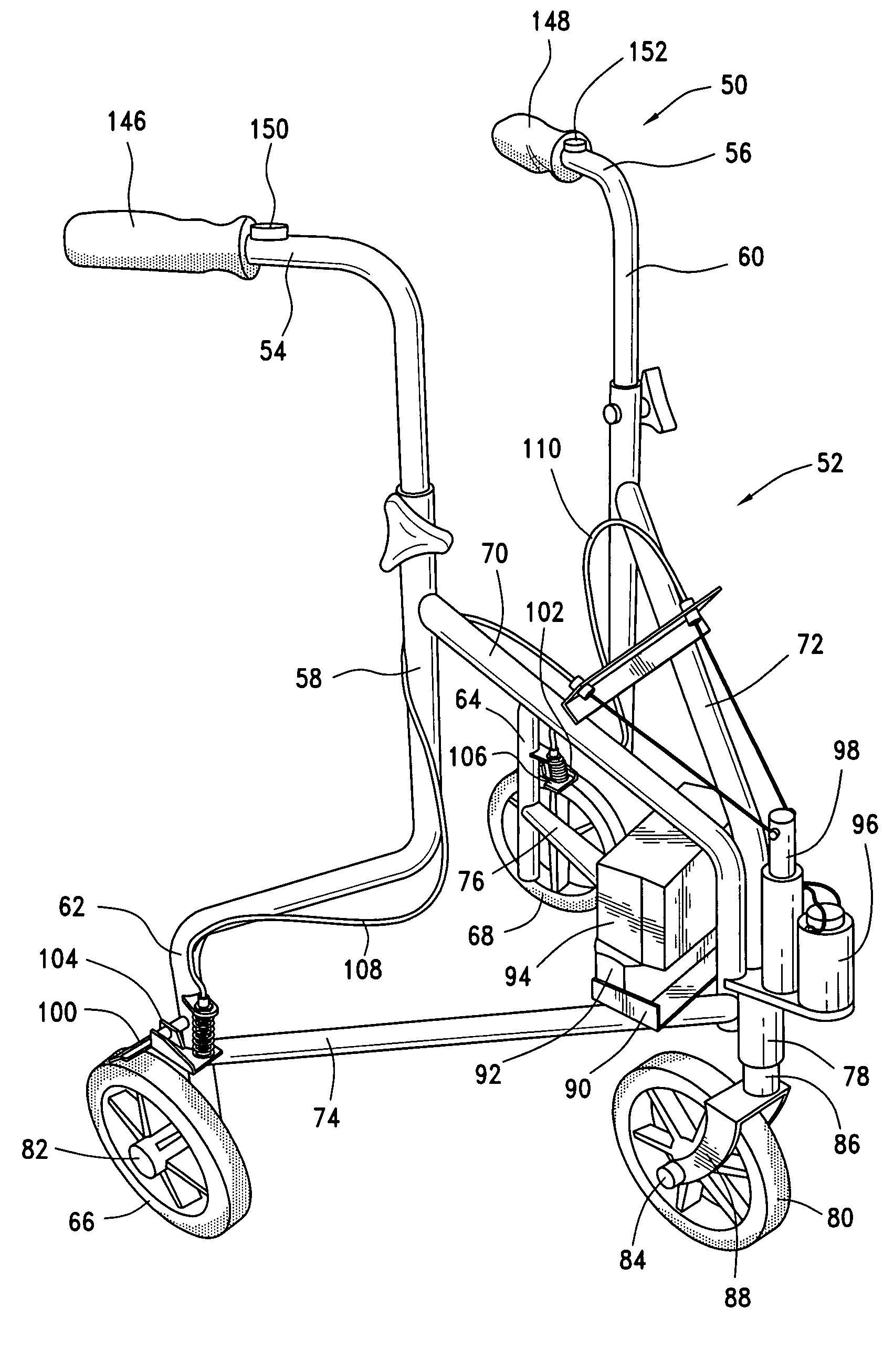
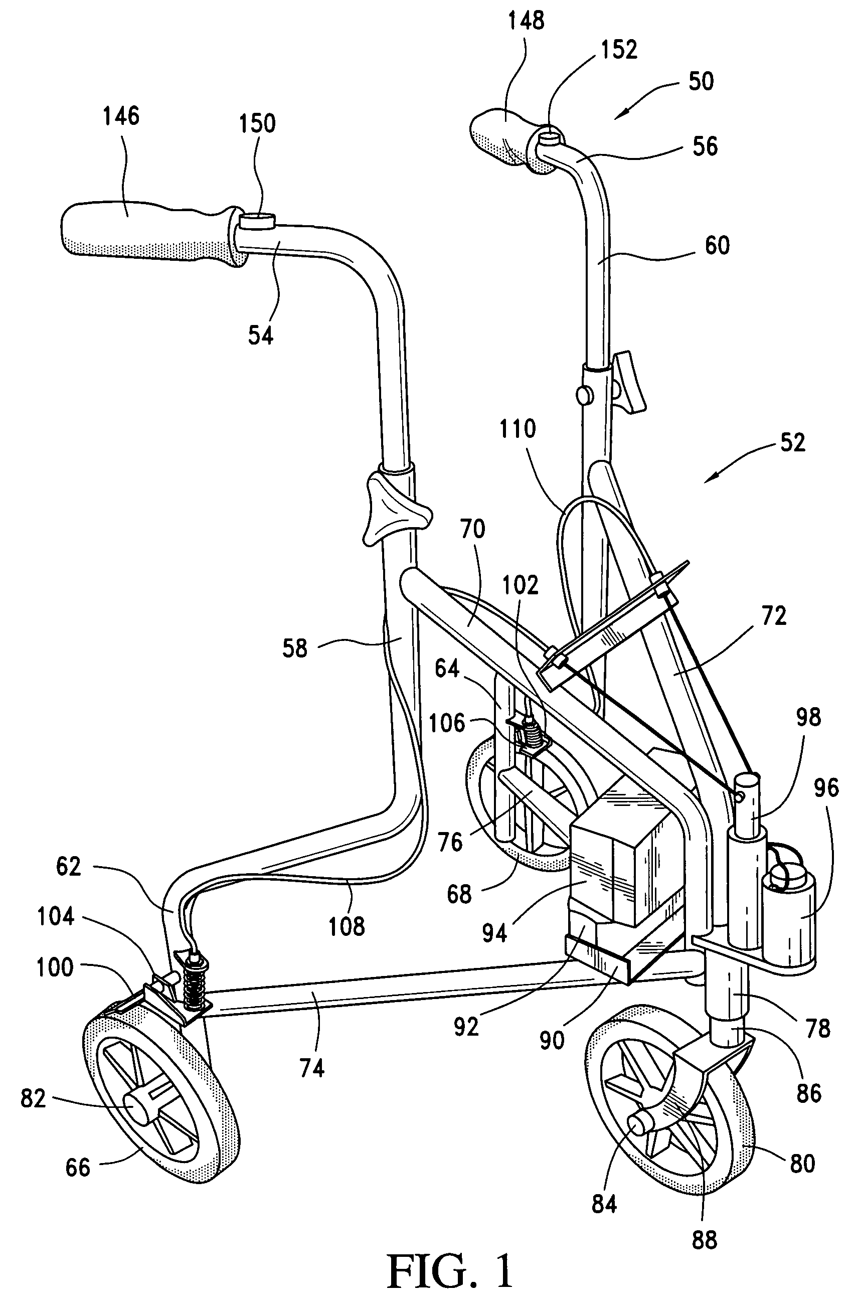
[0032]The invention is illustrated in FIG. 1 in combination with a three-wheeled walker, as illustrated at 50, and in combination with a four-wheeled walker as illustrated at 51 in FIG. 3, wherein common elem...


PUM


Abstract

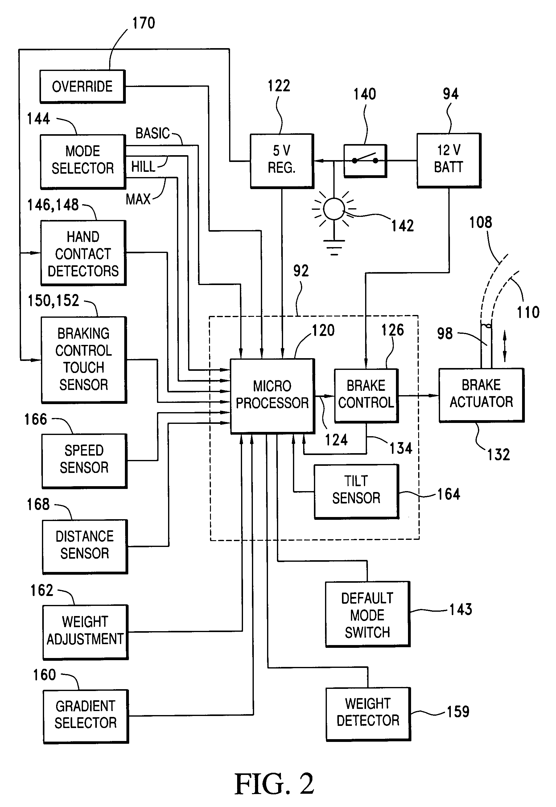
An improved electronic braking system for walkers that incorporates one or more electrically-operated brakes controlled by an electronic controller is disclosed. The controller is responsive to touch-sensitive switches for easy operation, and is adjustable and responsive to operator patterns of use to provide individualized control of the brake operation. The controller may also be responsive to environmental conditions such as the slope of the ground over which the walker is moving, to its rate of motion, or to the distance between the walker frame and the user, and may be adjusted to accommodate for the weight of the user or to set limits to the speed at which it can move.

Description

BACKGROUND OF THE INVENTION[0001]The present invention relates, in general, to methods and apparatus for controlling the movement of supportive wheeled vehicles of the type that ordinarily would be pushed or pulled by an operator, and, more particularly, to the application of such methods and apparatus to walking aids for weak but ambulatory people, for apparatus for adjusting such walking aids to meet the particular and evolving needs of such people, and more particularly to an improved electronically controlled braking system for such walking aids.[0002]A wide range of structures have been devised to assist people who find it difficult to walk unaided, and who may be lacking in strength or manual dexterity. A commonly-used structure for this purpose is customarily referred to as a walker, although various other structures such as wheel chairs, carts and the like are also available. The present invention will be described in conjunction with walkers, but it will be understood that ...

Claims


Application Information

Patent Timeline
Patent Type & Authority Patents(United States)
IPC IPC(8): B60T1/02
CPCA61H3/04B60T17/22F16C1/10A61H2003/046A61H2201/5058Y10T74/20438A61H2201/5079A61H2201/5071
Inventor EINBINDER, ELI
Owner EINBINDER ELI
Learn More