
Improved blowout preventer testing system and method

a blowout preventer and testing system technology, applied in the field of oil and gas production, can solve the problems of increased number of tests that must be conducted, long testing time, and long delays

Inactive Publication Date: 2010-04-27
BP CORP NORTH AMERICA INC
View PDF8 Cites 31 Cited by
  • Summary
  • Abstract
  • Description
  • Claims
  • Application Information

AI Technical Summary

Benefits of technology

[0028]Some of the advantages of the invention include simplicity and speed. Recent advances in digital technology and the relative ease of data processing with inexpensive personal computer (PC) technology lead to a clear opportunity for improvement in the recording, analysis, and validation of BOP tests. Numerous other advantages and features of the present invention will become readily apparent from the following detailed description of the invention, the embodiments described therein, from the claims and from the accompanying drawings.

Problems solved by technology

Industry trends toward deeper water, synthetic oil-based fluids, and subsurface conditions requiring increasingly higher test pressures all contribute to lengthy delays while waiting for pressures to stabilize during subsea BOP testing.
Also, subsea BOP stacks with redundancy of components and use of multiple-diameter drill strings leads to greater numbers of tests that must be conducted.
Pressure testing a BOP with SBM leads to lengthy testing times as a result of pressure / volume / temperature (PVT) influences associated with the fluid properties of SBM.
The problem of BOP testing has existed for some time.
Considerable time and effort is expended each year to perform BOP tests.
In spite of this, and with the exception of the earlier work by Franklin, et al., BOP testing schemes have not progressed in a long time.
Actually, the problem has become aggravated with the passage of time because each year more and more testing is conducted at higher pressures using the current time consuming processes.

Method used


Image

  • Improved blowout preventer testing system and method
  • Improved blowout preventer testing system and method
  • Improved blowout preventer testing system and method

Examples


Embodiment Construction

[0043]While this invention is a susceptible embodiment in many different forms, there is shown in the drawings, and will herein be described in detail, one specific embodiment of the invention. It should be understood, however, that the present disclosure is to be considered an exemplification of the principles of the invention and is not intended to limit the invention to any specific embodiment so described.

Digital BOP Testing Algorithm

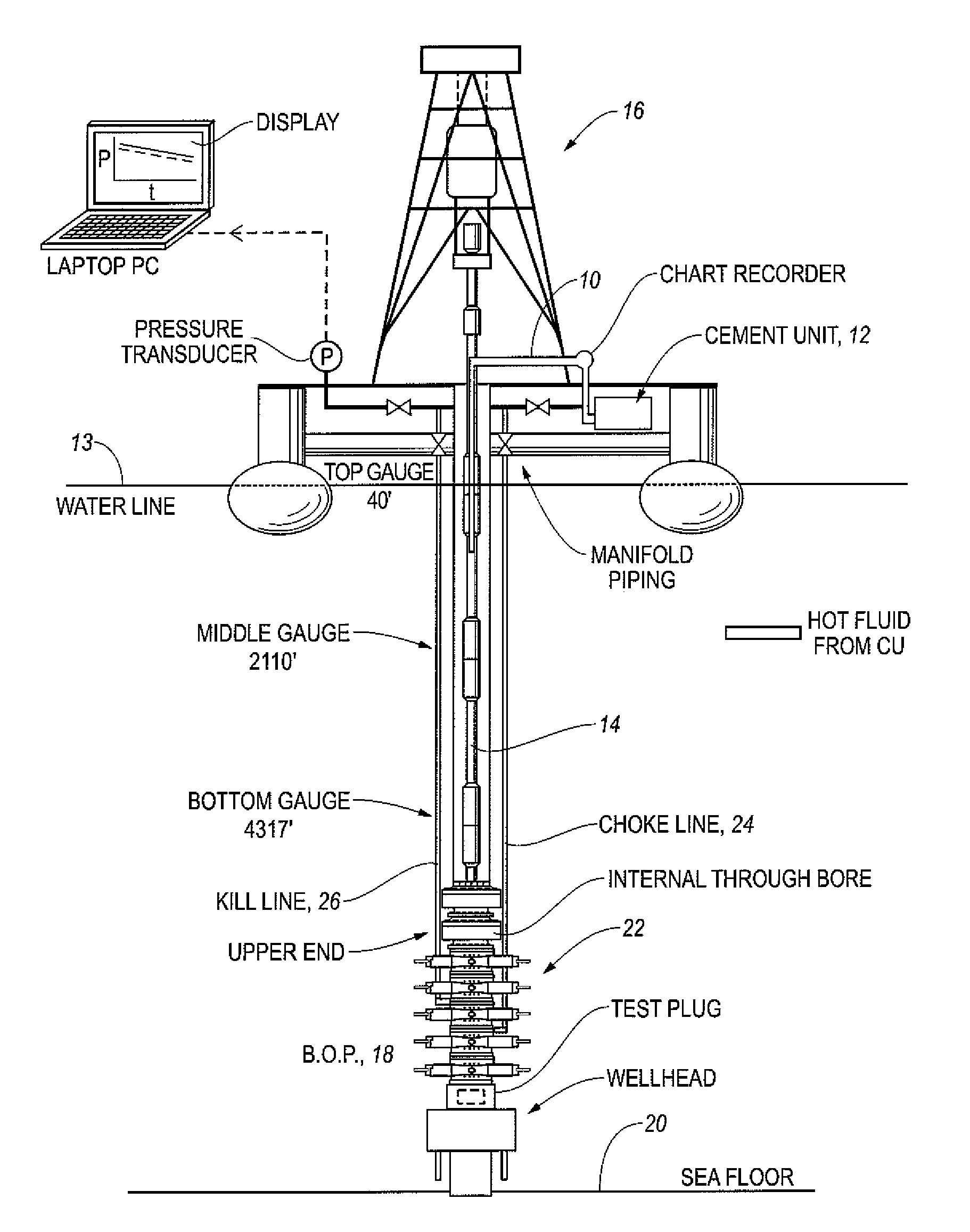
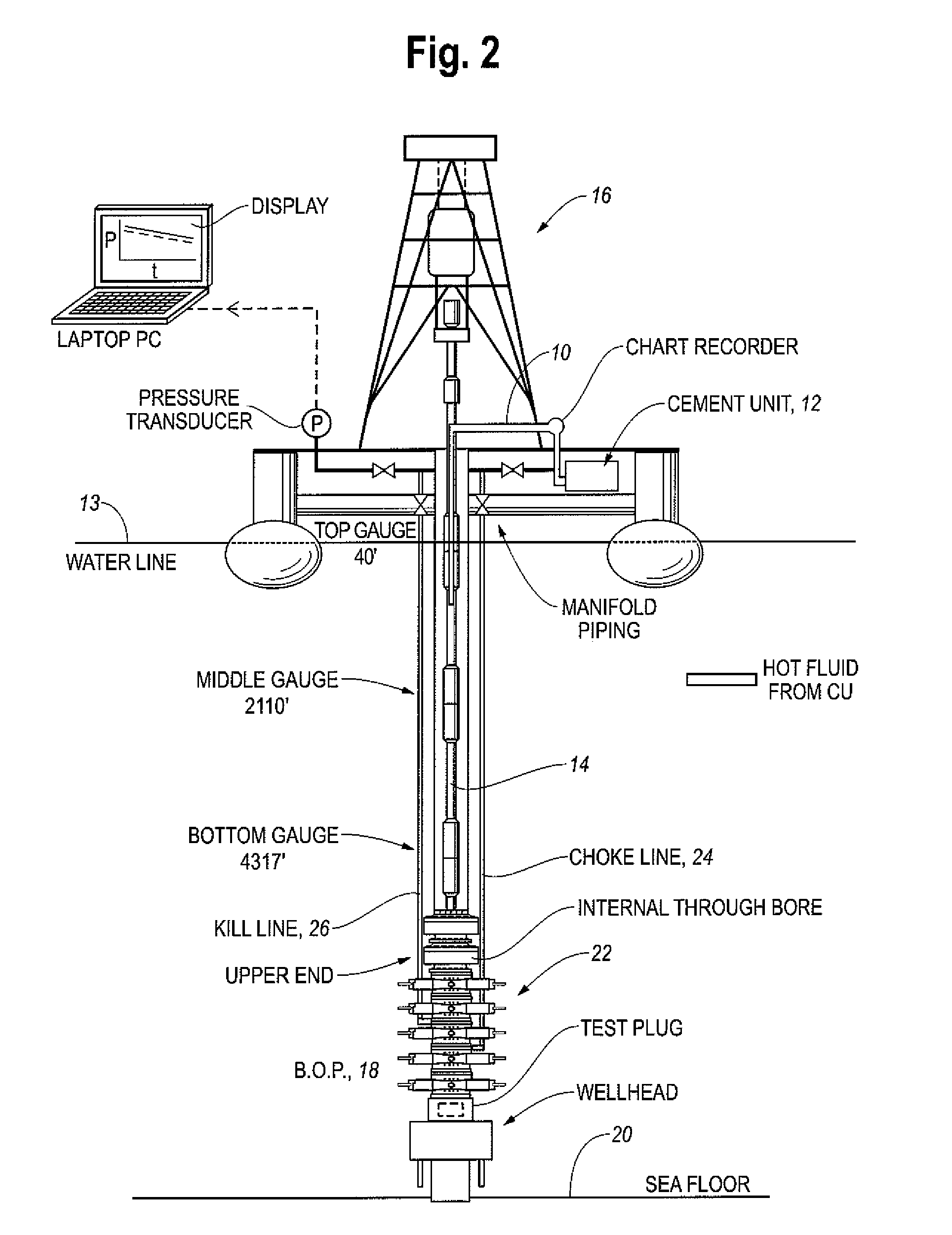
[0044]To enable real time interpretation of subsea blowout preventer tests, a digital BOP testing algorithm was developed. Many specific approaches may be taken; preferably, the algorithm should obtain accurate pressure forecasts and have good predictive capability. The algorithm is used to fit observed or actual pressure data, and a pressure trend is extrapolated. Finally, a test criteria is applied to check for confidence in the pressure forecast.

[0045]Pump rate, volume pumped and pump pressure data are received in approximately 1-second intervals...


PUM


Abstract

A method and apparatus for testing a blowout preventer (BOP) wherein a pressurization unit applies fluid to an isolated portion of the throughbore of the BOP. A signal that is representative of the actual pressure in the isolated portion of the throughbore over successive time points and a pre-determined non-deterministic finite state automaton are used to predict the pressure in the isolated portion of the throughbore as a function of time relative to a pre-determined acceptable leak rate and the time at which stability is achieved. In one embodiment stability is achieved when successive predicted pressures are within a predetermined difference over a predetermined interval of time. Visual indications are provided to depict the progress of testing.

Description

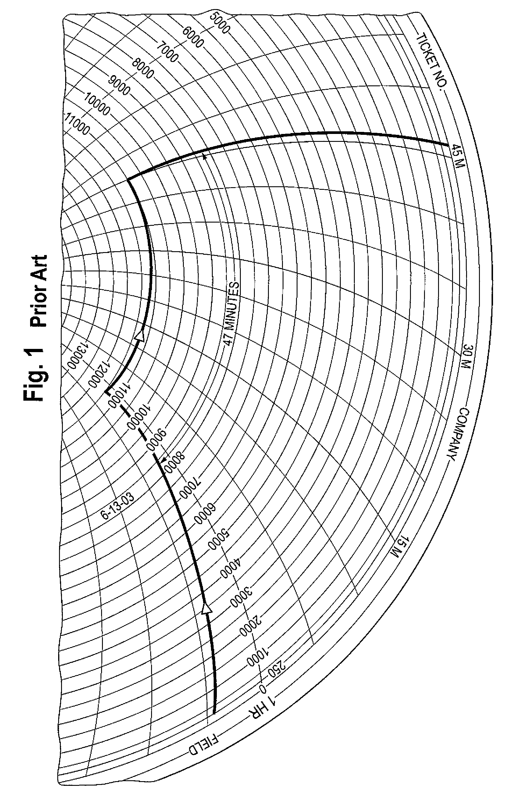
CROSS-REFERENCE TO RELATED APPLICATIONS[0001]This Patent Application is related to a pending U.S. patent application filed on Dec. 22, 2004 under Ser. No. 11 / 025,415 and published as 2005 / 0269079 on Dec. 8, 2005. The teachings therein are incorporated herein by reference. This patent application claims the priority of a USA Provisional Patent Application filed on Feb. 1, 2007 under Ser. No. 60 / 887,739 and entitled “Improved Blowout Preventer System.”TECHNICAL FIELD[0002]This invention relates to the general subject of production of oil and gas and, in particular, to methods and apparatuses for testing fluid systems.BACKGROUND OF THE INVENTION[0003]Current subsea Blow Out Preventer (BOP) testing practice (in U.S. “Oil and Gas Drilling Operation,” Subpart D, 30 C.F.R. Chapter II, current Edition; and generally worldwide) is to view shut-in test pressures on circular chart recorders and wait until a 5-minute period of reasonably stable pressures is obtained (see FIG. 1). Reasonably sta...

Claims


Application Information

Patent Timeline
Patent Type & Authority Patents(United States)
IPC IPC(8): G01V1/40
CPCE21B47/06E21B33/064
Inventor WINTERS, WARREN J.LIVESAY, RONALD B.
Owner BP CORP NORTH AMERICA INC
Learn More