Connector for plastic optical fiber

a technology of plastic optical fiber and connector, which is applied in the direction of optical fiber with multi-layer core/cladding, optics, instruments, etc., can solve the problems of inability to achieve the focusing task. achieve the effect of limited optical power loss between the optical fiber and the optical transceiver

Active Publication Date: 2010-04-20
COMOSS ELECTRONICS
View PDF7 Cites 0 Cited by
  • Summary
  • Abstract
  • Description
  • Claims
  • Application Information

AI Technical Summary

Benefits of technology

[0007]It is an object of the present invention to provide a plastic optical fiber connector so that an optical fiber having an optical fiber core may be effectively and precisely connected to an optical transceiver via the optical fiber core and thus an optical power loss occurred between the optical fiber and the optical transceiver can be limited.
[0008]It is another object of the present invention to provide a plastic optical fiber connector whose structure cost are simple and low respectively.
[0010]The optical fiber connector has a plate body formed therein. On the plate body, a focusing hole is formed, the focusing body having a holding portion extending outwardly from a side thereof. With provision of the plate body, two reception spaces are formed in the optical fiber connector, with one of which having the seat body on which an optical transceiver is provided therein, wherein a transceiver terminal of the optical transceiver is bonded to the focusing hole on the plate body. Further, the wire seat is sleeved within the optical fiber connector so that the holding portion is allowed to be placed into an optical fiber guiding hole of the wire seat. When an optical fiber having optical fiber core is desired to be inserted into and thus connected to the optical fiber connector, the optical fiber core can be precisely inserted into the transceiver terminal of the optical transceiver via the focusing hole and the optical fiber guiding hole.

Problems solved by technology

However, since the cladding has a relatively larger tolerance, the focusing task tends to be difficult when an optical fiber core of the plastic optical fiber has a relatively smaller diameter.
In this case, an intolerable optical power loss may occur between the optical fiber and the optical transceiver and thus deficiency may be found in the coupling between the optical fiber and optical transceiver may be found.
In view of the above, the coupling between the optical fiber and optical transceiver has its disadvantage and needs to be improved.

Method used


Image

  • Connector for plastic optical fiber
  • Connector for plastic optical fiber
  • Connector for plastic optical fiber

Examples


Embodiment Construction

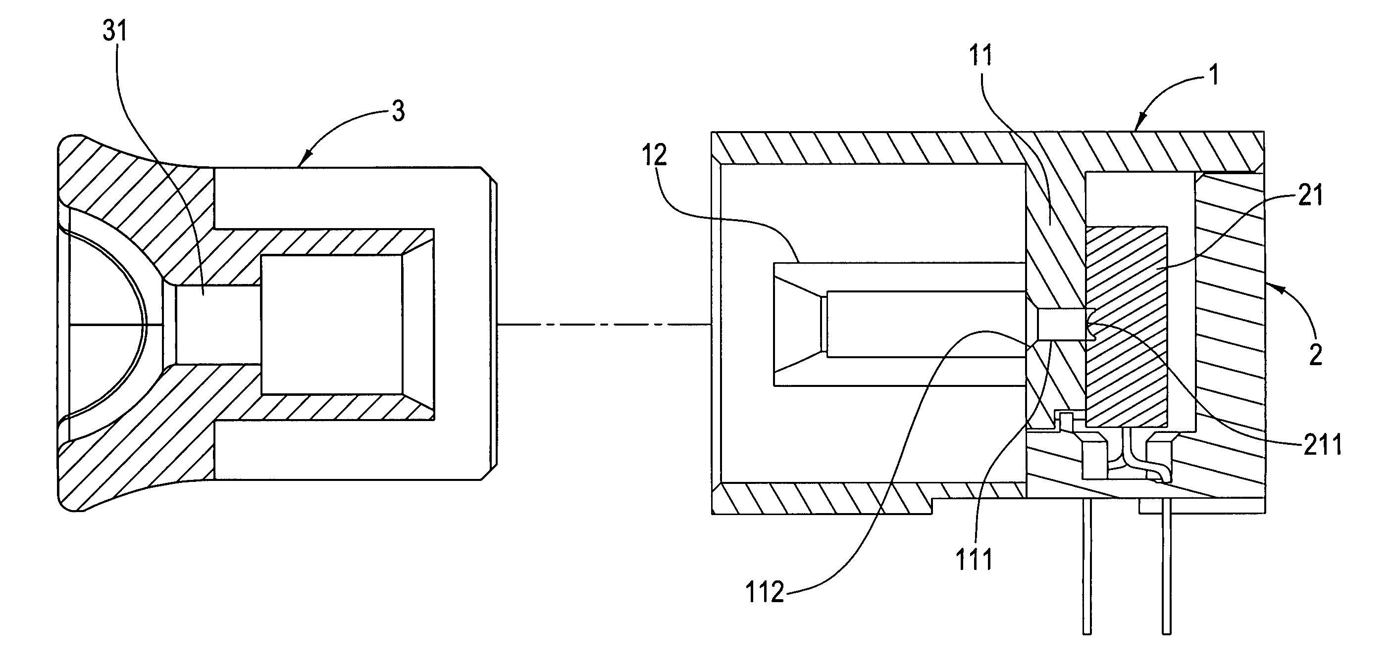
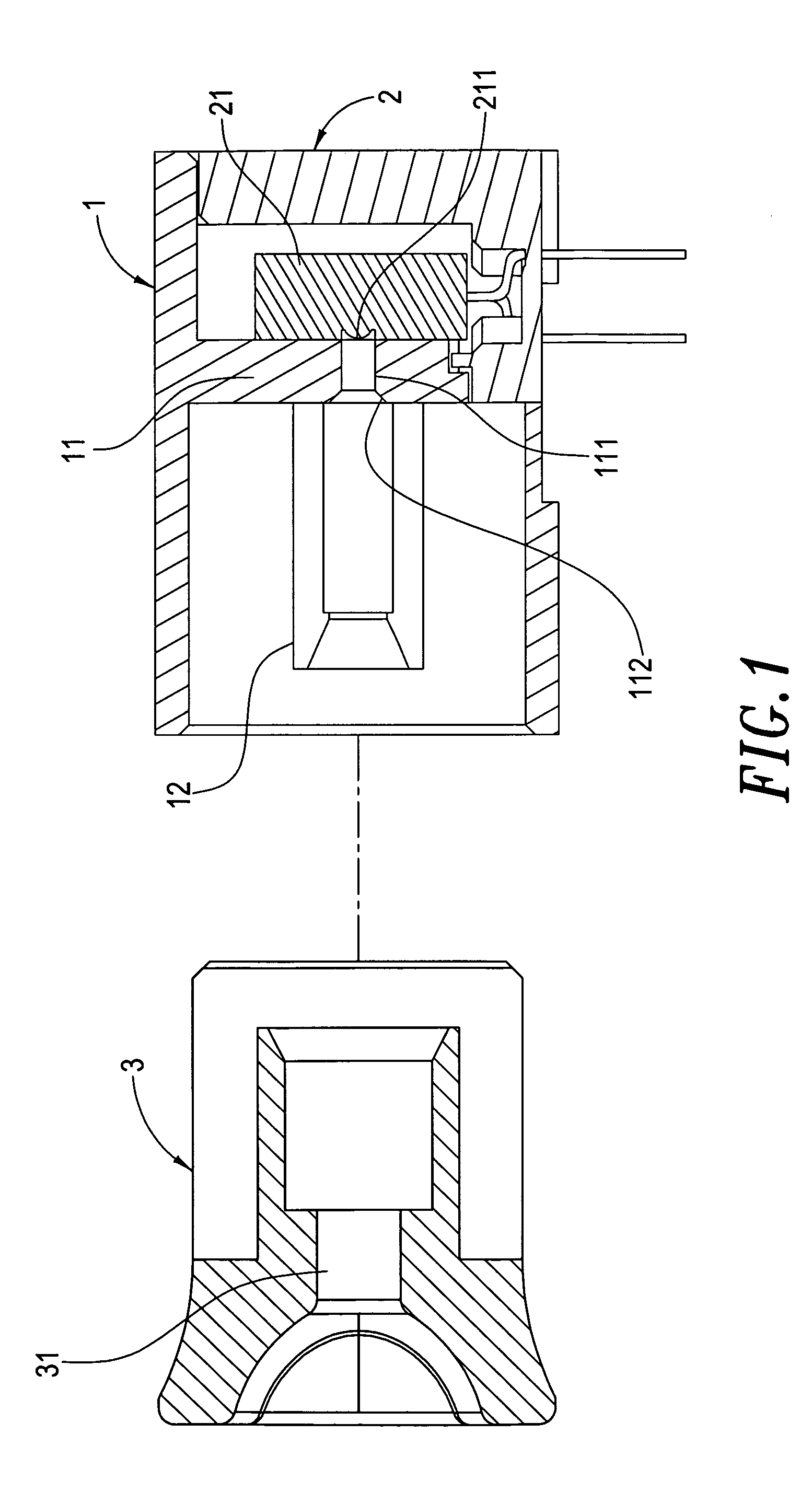
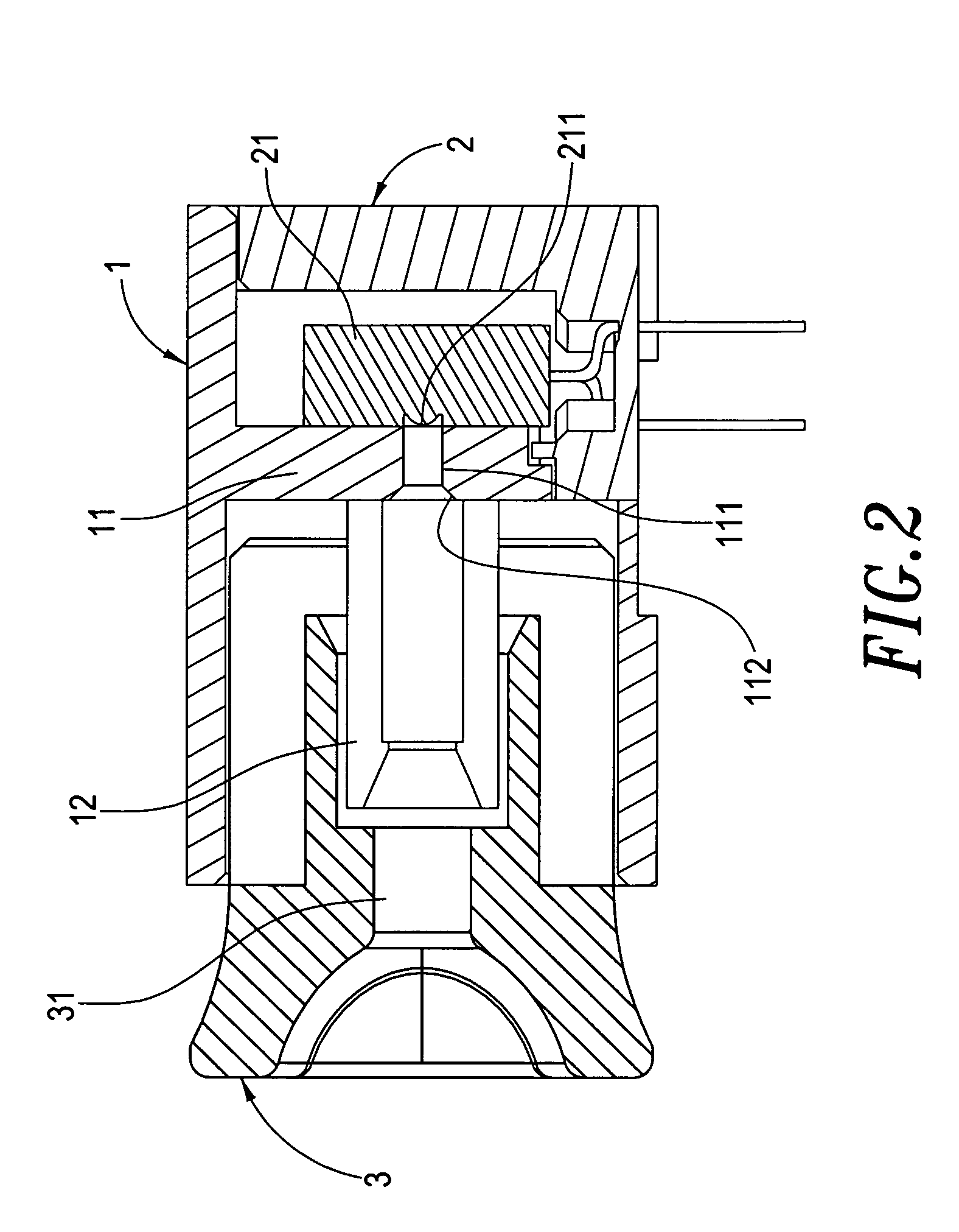
[0015]Referring to FIG. 1 through FIG. 3, a plastic optical fiber is provided in the present invention and whose structure and constituent components will be described with reference to the figures. An optical fiber connector 1 has a plate body 11 therein. On the plate body 11, a focusing hole 111 is formed at an adequate position. A holding portion 12 extends outwardly from a side of the focusing hole 111. On the focusing hole 111, a guiding face 112 is provided. Via the guiding face 112, an optical fiber 4 having optical fiber core 41 can be precisely guided into the hole 111. Meanwhile, the holding portion 12 can hole the optical fiber 4.

[0016]A seat body 2 has an optical transceiver 21 formed thereon and is formed in the optical fiber connector 1. The optical transceiver 21 has a transceiver terminal 211 formed at a front side thereof. Further, the transceiver terminal 211 is bonded to another side of the focusing hole 111 of the plate body 11.

[0017]A wire seat 3 is sleeved with...


PUM


Abstract

A plastic optical fiber connector includes an optical fiber connector having a plate body formed therein. On the plate body, a focusing hole is formed, the focusing hole having a holding portion extending outwardly from a side thereof. With provision of the plate body, two reception spaces are formed in the optical fiber connector, with one of which having a seat body on which an optical transceiver is provided therein, wherein a transceiver terminal of the optical transceiver is bonded to the focusing hole on the plate body. Further, a wire seat is sleeved within the optical fiber connector so that the holding portion is allowed to be placed into an optical fiber guiding hole of the wire seat.

Description

BACKGROUND OF THE INVENTION[0001]1. Field of the Invention[0002]The present invention is related to a plastic optical fiber connector, particularly to a plastic optical fiber connector in which a focusing hole can effectively and precisely align and connect an optical fiber core of an optical fiber to an optical transceiver when they are desired to be connected to each other.[0003]2. Description of the Prior Art[0004]Plastic optical fiber is an optical fiber having an excellent curvature and easy to be set up on spot, making itself widely applicable and realization of fiber to the home (FTTH) possible.[0005]A plugless optical transceiver has been suggested, to which an optical fiber can be connected directly. A sheath or jacket is provided as a cladding on such optical fiber and relied upon for alignment and focusing with the optical transceiver. However, since the cladding has a relatively larger tolerance, the focusing task tends to be difficult when an optical fiber core of the p...

Claims


Application Information

Patent Timeline
Patent Type & Authority Patents(United States)
IPC IPC(8): G02B6/036
CPCG02B6/3809G02B6/4292G02B6/4202G02B6/4246
Inventor TSAI, EDEN
Owner COMOSS ELECTRONICS
Why Eureka
Try Eureka