Screw-retaining screwdriver

a screwdriver and screw technology, applied in the field of screwdrivers, can solve problems such as the blade being unable to retain the screw

Active Publication Date: 2010-04-06
SYNTHES GMBH
View PDF19 Cites 10 Cited by
  • Summary
  • Abstract
  • Description
  • Claims
  • Application Information

AI Technical Summary

Benefits of technology

[0009]In a further embodiment the screwdriver contains a nub extending beyond the proximal end of the tip along the longitudinal axis of the apparatus. The nub engages a corresponding recess in a screw head assisting in guiding the blade into place in operation.
[0011]In yet another embodiment the screwdriver contains blades that are tapered along the longitudinal axis with the taper having its narrowest point at the proximal end of the apparatus. The taper assists in creating a secure fit between the blade and the screw slot when the

Problems solved by technology

This offset causes a friction force between the blades and a screw slot when the blade is inserted into the screw slot with force, causing the blade to retain the screw.

Method used


Image

  • Screw-retaining screwdriver
  • Screw-retaining screwdriver
  • Screw-retaining screwdriver

Examples


Embodiment Construction

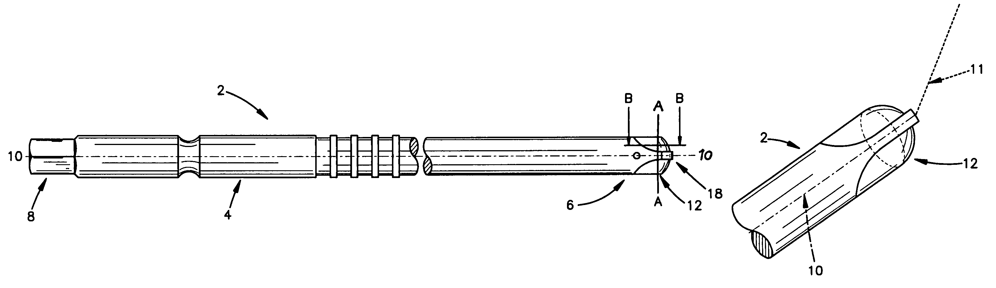
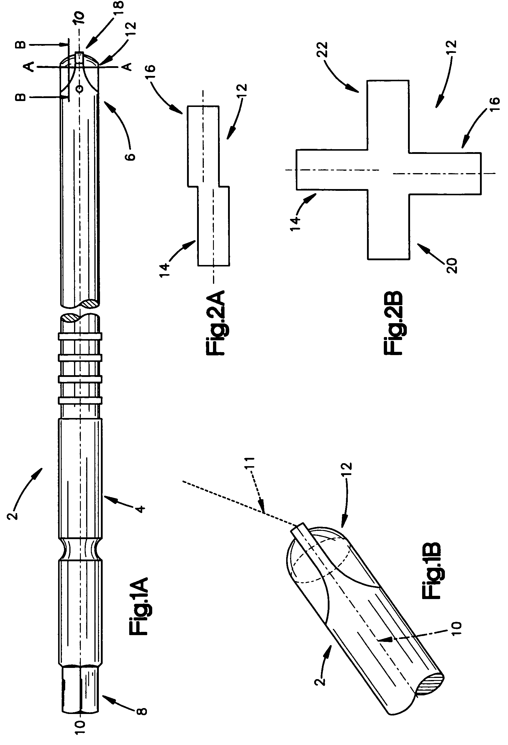
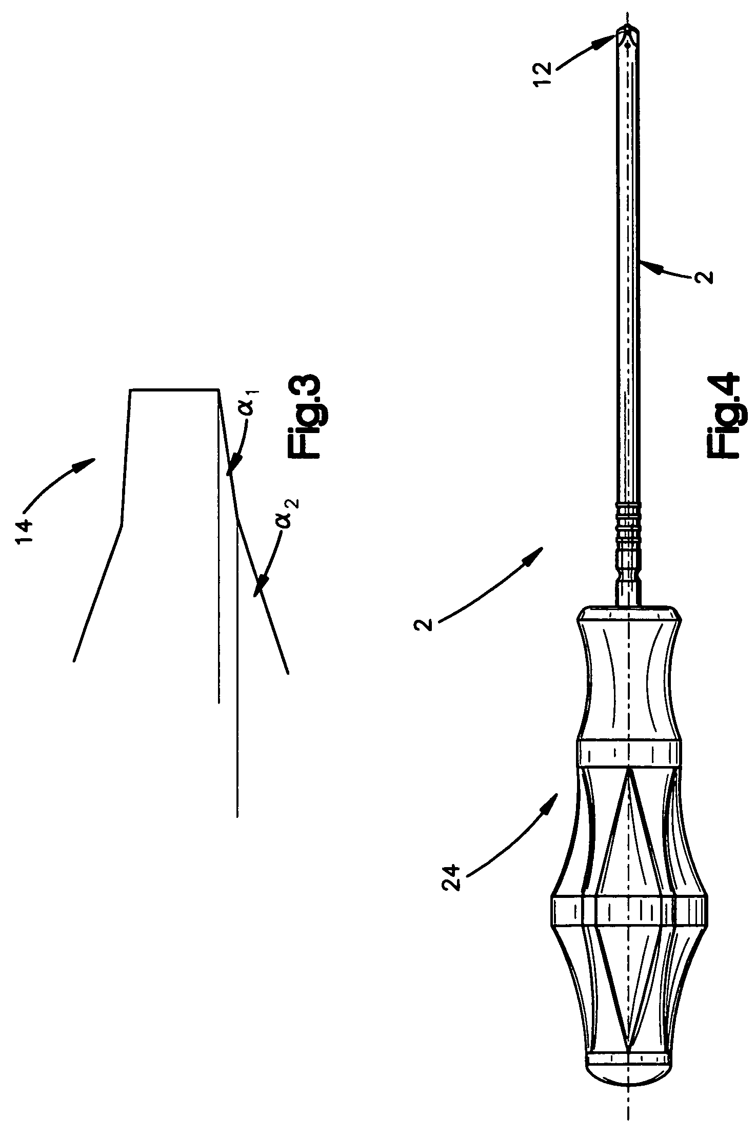
[0020]FIG. 1A shows a screwdriver 2 suitable for the present invention. The screwdriver 2 may include an elongated member 4 with a proximal end 6, a distal end 8 and which defines the longitudinal axis 10 of the screwdriver. A tip 12 may extend from the proximal end 6 of the elongated member 4 along the longitudinal axis 10.

[0021]FIG. 1B shows the tip 12 of the screwdriver 2 of FIG. 1A in more detail. Specifically, the spherically cut tip 12 may allow the blades of the screwdriver 2 to pivot in the recess of a screw so that the screw may be driven in an axis 11 not aligned with the longitudinal axis 10 of the screwdriver 2. This may be beneficial in minimally invasive or otherwise difficult procedures.

[0022]As seen in more detail in FIG. 2A, the tip 12 may have at least a first blade 14 and a second blade 16 each with a surface perpendicular to the longitudinal axis 10 of the elongated member 4. The first and second blade 14, 16 may be substantially opposite about the longitudinal a...


PUM


Abstract

A screwdriver having a retention mechanism for temporarily holding a screw in place on its tip while the screw is being positioned, rotated or removed. More particularly, a screwdriver with a cruciform head used in the installation and removal of bone screws during maxillofacial surgery.

Description

CROSS-REFERENCE TO RELATION APPLICATION[0001]This application is a continuation of U.S. Provisional Application No. 60 / 705,668, filed Aug. 3, 2005, the entirety of which is incorporated by reference herein.FIELD OF THE INVENTION[0002]The invention relates to a screwdriver having a retention mechanism for temporarily holding a screw in place on it tip while the screw is being positioned, rotated or removed. More particularly, the invention relates to a screwdriver with a cruciform head used in the installation and removal of bone screws during maxillofacial surgery.BACKGROUND OF THE INVENTION[0003]A variety of medical procedures, such as maxillofacial surgery, require the use of screws that are driven into a patient's bone and may at a later time be removed. Prior to being driven into the bone the screw must be maneuvered into place and following removal of the screw it is necessary to maneuver the screw out of the body without dropping the screw. A dropped screw may become lost insi...

Claims


Application Information

Patent Timeline
Patent Type & Authority Patents(United States)
IPC IPC(8): B25B23/10
CPCA61B17/8886A61B17/8888B25B23/108B25B15/005A61C8/0089A61B17/88B25B15/00
Inventor GRIFFITHS, BRYAN
Owner SYNTHES GMBH
Why Eureka
Try Eureka