Filtration device combined with self-priming pump

a technology of filtration device and self-priming pump, which is applied in the direction of filtration separation, liquid fuel engines, separation processes, etc., can solve the problems of difficult to extract the filter with liquid dripping, complicated and dangerous, and achieve the effect of suppressing impeller performance deterioration and ensuring liquid tightness in the pump uni

Active Publication Date: 2010-03-23
WORLD CHEM CO LTD
View PDF9 Cites 1 Cited by
  • Summary
  • Abstract
  • Description
  • Claims
  • Application Information

AI Technical Summary

Benefits of technology

[0008]Therefore, an object of the present invention is to provide a filtration device combined with self-priming pump in which a filter replacement work is easy and safe, and removal of air inside of the pump and priming are not necessary.
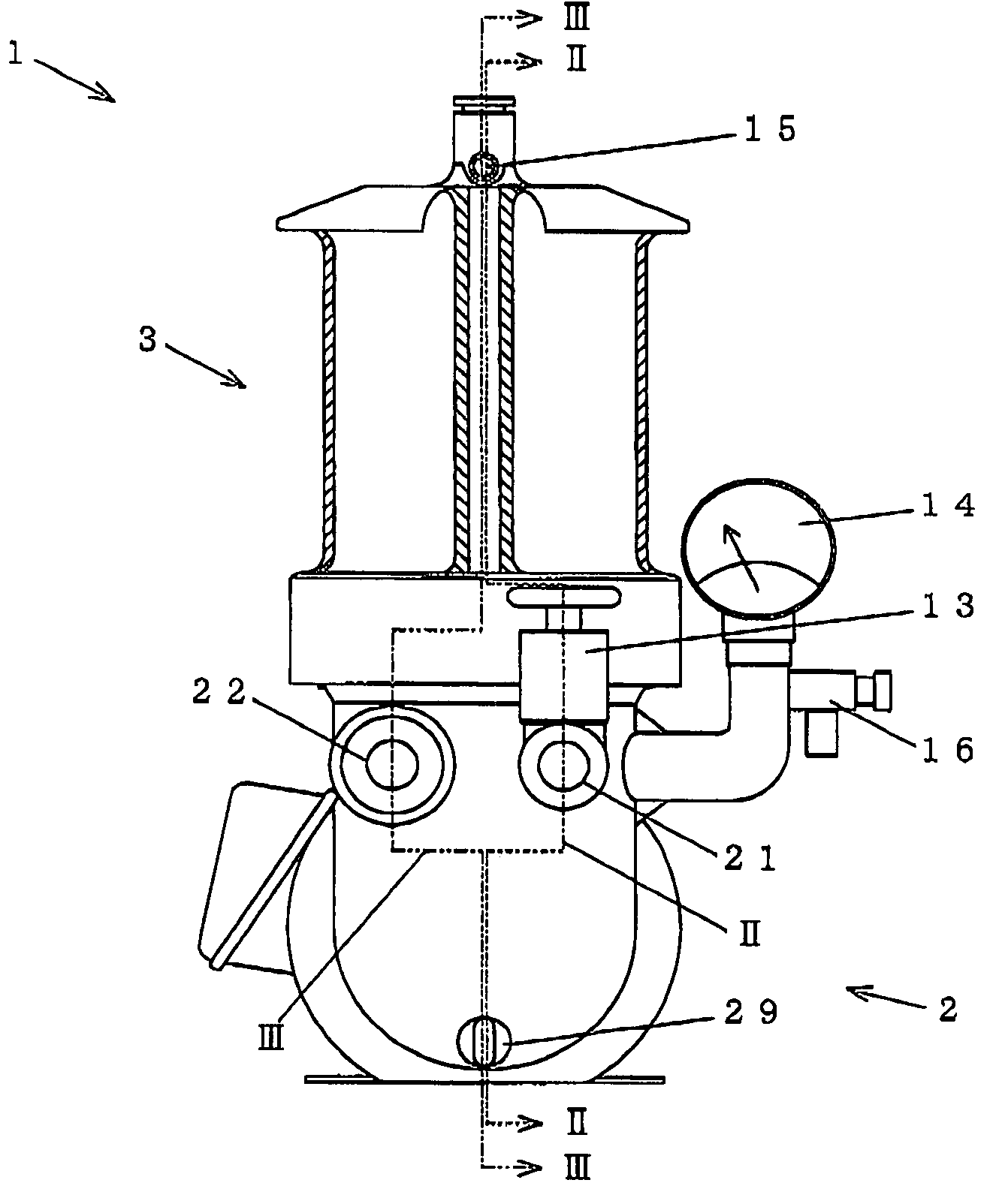
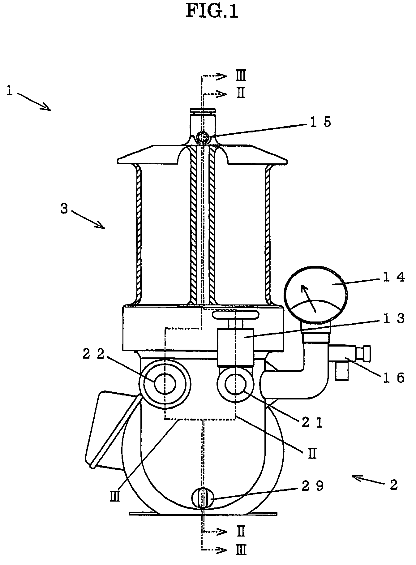
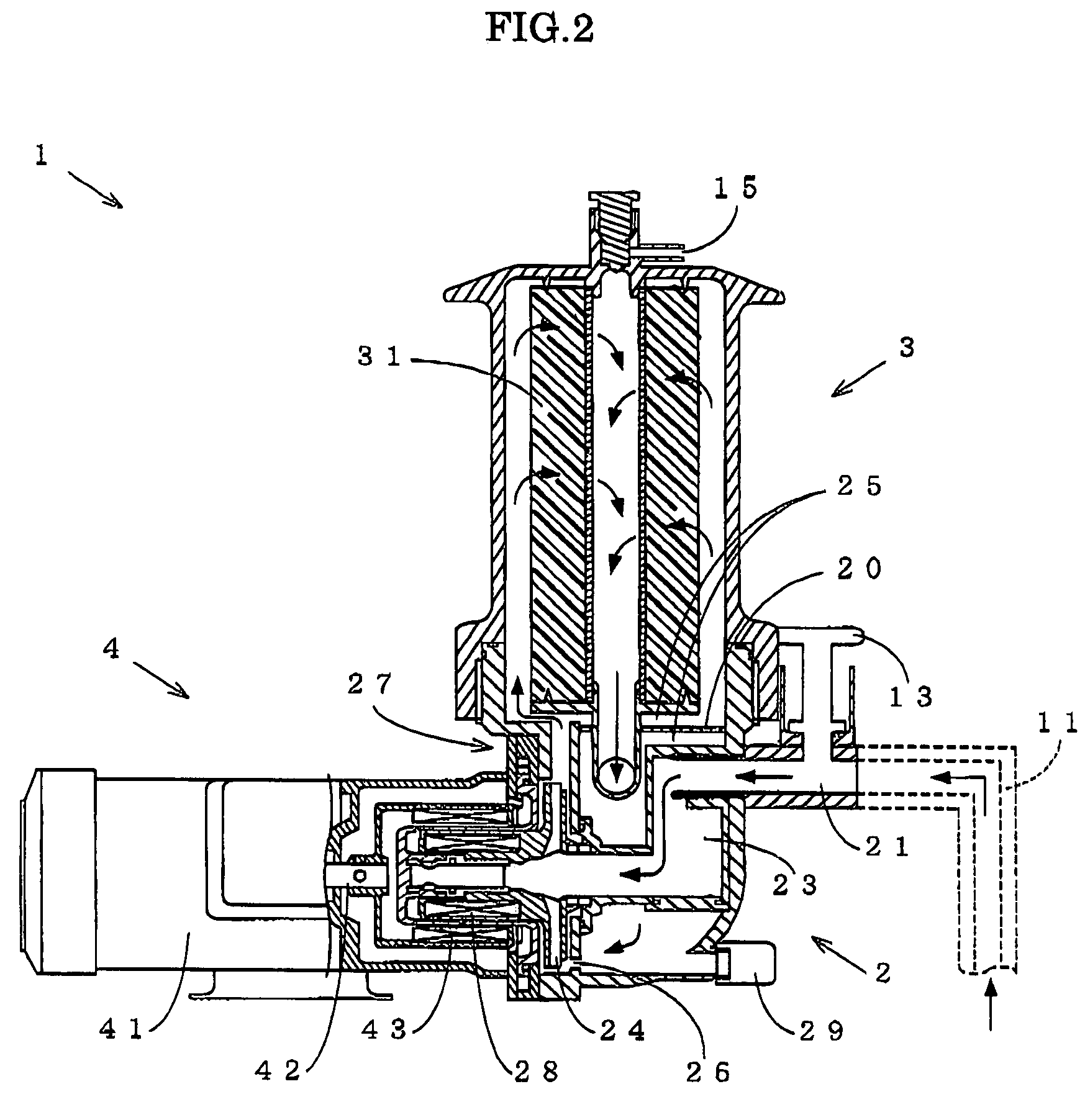
[0019]According to the invention of the above (1), the filtration device combined with self-priming pump is configured to include a pump unit, which is a valveless-construction self-priming pump without a check valve, including: a suction port, a suction chamber, an impeller, a self-priming chamber, a discharge port from an upstream of a channel to a downstream thereof in this order, the suction port and the discharge port being arranged above the level of the suction chamber and the impeller, and a self-priming chamber arranged above the level of the suction port and the discharge port; a filtration unit arranged on a channel between the self-priming chamber and the discharge port and above the level of the self-priming chamber; and a filter arranged inside of the filtration unit and above the level of residual liquid inside of the pump unit at the time of suspending of the pump unit. Thus, at the time of suspending the operation, the liquid inside of the filtration unit is discharged and flown back so that the liquid is emptied, and the liquid accumulated or adhering in the mesh of the filter or on the surface thereof is also flown out. As a result, without performing liquid drainage or the like from a drain, the filter inside of the filtration unit can be extracted and replaced without causing liquid dripping. Therefore, the filter replacement work can be performed very easily, without contaminating a worker or surrounding areas of the device. In particular, even when the liquid is a dangerous chemical, the filter replacement work can be performed without creating risk.
[0021]According to the invention of the above (2), the filtration unit is configured to be arranged above the self-priming chamber, and thus, the self-priming chamber and the filtration unit can be easily arranged in a connecting state and on the channel between the discharge port and the self-priming chamber.
[0023]According to the invention of the above (4), the pump unit and the filtration unit are configured as one unit, and thus, it is possible to achieve further miniaturization and a simpler configuration, as compared to a separate-type configuration.
[0026]According to the invention of the above (7), a drive unit of the pump unit is a magnet-coupling type drive unit, and thus, liquid tightness in the pump unit can be ensured.
[0027]According to the invention of the above (8), in the inside of the self-priming chamber, a perforated plate for separating air and liquid is arranged. Thus, by separating the air from the liquid containing air, the air separated from the liquid moves upward and the liquid in which the air is separated can be moved downward. As a result, it becomes possible to suppress a performance deterioration of the impeller caused due to a decrease in centrifugal force when the liquid containing the air enters.

Problems solved by technology

However, this operation has a drawback in that collection of the liquid drained from the drain needs to be performed manually by using a bucket or the like, and thus, this is not only complicated but also dangerous depending on the type of liquid.
Another drawback is that the filter that has been submerged in the liquid prior to the liquid drainage causes dripping of accumulated liquid left on the surface or inside of the filter even when the liquid drainage is performed.
Thus, a worker and areas surrounding the device are not only contaminated, but also it is difficult to extract the filter with liquid dripping, and the replacement work is complicated and troublesome.
Further, danger may be involved depending on the type of liquid.
Still another drawback is that, upon resuming the operation after the replacement of the filter, removal of air inside of the pump and priming are necessary.
Thus, it is not only time-consuming but it also makes an operation suspension time long.

Method used


Image

  • Filtration device combined with self-priming pump
  • Filtration device combined with self-priming pump
  • Filtration device combined with self-priming pump

Examples


second embodiment

[0050]Subsequently, the present invention is described according to the FIG. 4.

[0051]FIG. 4 shows the second embodiment of the filtration device 1A of the present invention, a pump unit 2A and a filtration unit 3A is formed in a separate unit, two units are connected each other, namely, the filtration unit 3A is connected above the pump unit 2A through the discharge port 22A of the pump unit 2A. And, the filtration unit 3A is formed similarly as the filtration unit 3 in the first embodiment.

first embodiment

[0052]For the pump unit 2A, similar to the first embodiment, a publicly known and used valveless-construction self-priming pump without a check valve that needs no priming and removal of air at the time of resuming its operation, may be adopted. A “self-priming chemical pump” described in Japanese Patent No. 2665140, which is a technology proposed by the present applicant, and other self-priming pumps already existing and installed can be used therefor.

[0053]The pump unit 2A preferably is configured to include a drive unit configured similarly to the drive unit 4 in the first embodiment or a drive unit publicly known and used as a drive unit for a self-priming pump of this type.

[0054]As described above, the filtration unit 3A has a filter 31A arranged inside thereof, similarly to the filtration unit 3 in the first embodiment. The filter 31A is to be arranged and positioned above the level of the residual liquid inside of the pump unit 2A at the time of suspending the operation of th...


PUM

PropertyMeasurementUnit
timeaaaaaaaaaa
areaaaaaaaaaaa
suctionaaaaaaaaaa

Abstract

The present invention provides a filtration device combined with self-priming pump in which a filter replacement work is easy and safe, and removal of air inside of a pump and priming are not necessary. And this filtration device is characterized to provide with a pump unit, which is a valveless-construction self-priming pump without a check valve, including a suction port, a suction chamber, an impeller, a self-priming chamber, a discharge port from an upstream of a channel to a downstream thereof in this order, the suction port and the discharge port being arranged above the level of the suction chamber and the impeller, and a self-priming chamber arranged above the level of the suction port and the discharge port; a filtration unit arranged on a channel between the self-priming chamber and the discharge port and above the level of the self-priming chamber; and a filter arranged inside of the filtration unit and above the level of residual liquid inside of the pump unit at the time of suspending of the pump unit.

Description

FIELD OF THE INVENTION[0001]The present invention relates to a filtration device combined with self-priming pump.DESCRIPTION OF THE PRIOR ART[0002]In chemical and other fields, filtration devices are generally used as a means for removing impurities from various kinds of liquids. In particular, as a filtration device provided with a pump in which liquid retained in a tank or the like is suctioned, the suctioned liquid is filtered through a filter, and then delivered to a post-process, or delivered back to the tank for circulation, a filtration device provided with a push pump with a foot valve is known (See: Japan Patent Pre-Publication No. 2005-238071 and Japan Patent Pre-Publication No. 2004-188337).[0003]On the other hand, as a valveless-construction self-priming pump, a self-priming chemical pump is known (See: Japan Patent No. 2665140).SUMMARY OF THE INVENTION[0004]In the filtration devices disclosed in the above mentioned Japan Patent Pre-Publication No. 2005-238071 and No. 20...

Claims


Application Information

Patent Timeline
Patent Type & Authority Patents(United States)
IPC IPC(8): F03B11/00
CPCB01D35/26F04D29/708F04D9/02F04D9/005
Inventor MORI, YOJISASAKI, TAKASHIHAGA, YASUICHI
Owner WORLD CHEM CO LTD
Why Eureka
Try Eureka