
Dynamically self-balanced fluid turbine

a fluid turbine and self-balancing technology, applied in the direction of circumferential flow pumps, wind motors with parallel air flow, perpendicular air flow, etc., can solve the problems of perennial searching loops overshooting the maxima, using a vane, and inefficient efficiency

Inactive Publication Date: 2010-03-23
PAUL MARIUS ANGELO
View PDF4 Cites 14 Cited by
  • Summary
  • Abstract
  • Description
  • Claims
  • Application Information

AI Technical Summary

Problems solved by technology

Using a vane, however, has proven to be inefficient and achieves orientation slowly often lagging the actual orientation of the fluid flow.
Generally, these algorithms suffer from perennial searching loops overshooting the maxima in a manner characteristic of either under- or over-damped oscillatory systems.
In either of the vaned or the actuated systems, searching inefficiencies can denigrate performance of reactive turbine as function of the available kinetic energy of the driving fluid.

Method used


Image

  • Dynamically self-balanced fluid turbine
  • Dynamically self-balanced fluid turbine
  • Dynamically self-balanced fluid turbine

Examples


Embodiment Construction

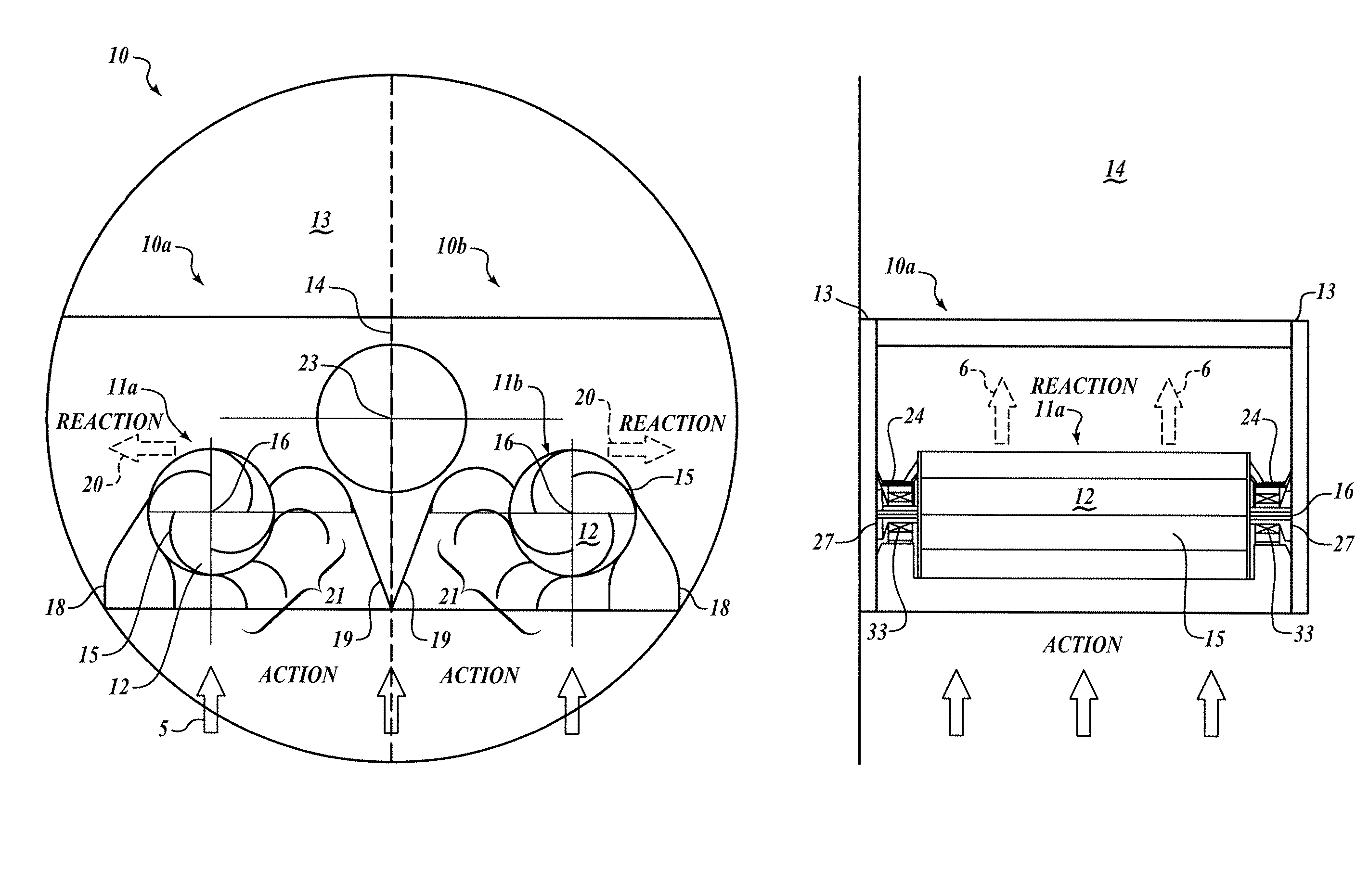
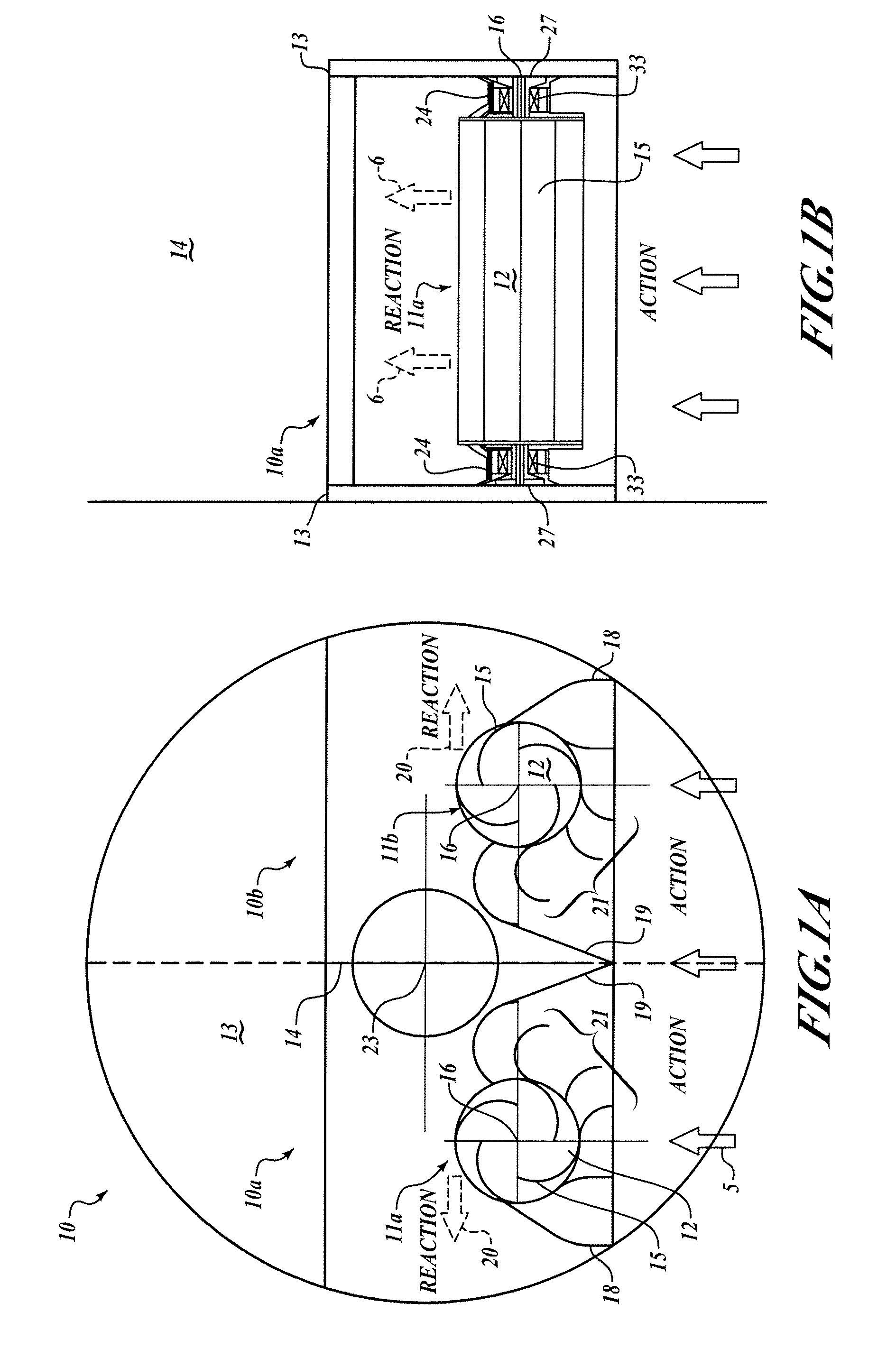
[0015]A self-orienting casement pressure casement comprises a first and a second turbine spinning in opposite directions to produce generally balanced and opposing torques about an orientation axis. As a flow of fluid along a fluid flow vector drives the first and second turbines, imbalances occur between the loading of the first and second turbine. Generally these imbalances are the result of the orientation of the casement deviating from the orientation of the fluid flow vector. The resulting differences in torque between the first and the second turbines tends to reorient the casement to align with the fluid flow vector resulting in stable equilibrium as the imparted torque from the first and second turbines balance each other.

[0016]Referring to FIG. 1a, a cross-section of the orientable turbine casement 10, the symmetry of the elements of the orientable turbine casement 10 about a casement plane 14, is evident. The casement plane 14 is set forth to define a plane of symmetry and...


PUM


Abstract

A system and method for orienting first and second reaction turbines relative to an axis of rotation responds to a fluid flow having a flow orientation axis. The fluid flow is received in a casement. The casement has first and second endplates situated parallel and spaced apart along the axis of rotation. A first half of the fluid flow drives the first reaction turbine to rotate with a first spin orientation in a plane perpendicular to the axis of rotation to produce a first torque about the axis of rotation. The second half of the fluid flow drives the second reaction turbine, offset from the casement plane relative to the first reaction turbine, with a second spin orientation opposite the first spin orientation to produce a second torque about the axis of rotation. The casement is oriented about the axis of rotation in response to the first and second torques.

Description

PRIORITY CLAIM[0001]This Application claims priority from provisional application Ser. No. 60 / 760,232 with a filing date of Jan. 18, 2006 and having the title, “Universal Fluid Dynamic Power System and Desalination.” This reference incorporates that application in its entirety in this application.FIELD OF THE INVENTION[0002]This invention relates generally to turbine technology and, more specifically, to fluid-driven reaction turbines.BACKGROUND OF THE INVENTION[0003]The operation of reaction turbines is described by Newton's third law of motion (action and reaction are equal and opposite). In a reaction turbine, unlike in an impulse turbine, the nozzles that discharge the working fluid are attached to the rotor.[0004]The acceleration of the fluid leaving the nozzles produces a reaction force on a turbine rotor, causing the rotor to move in the opposite direction to that of the fluid. The pressure of the fluid changes as it passes through the rotor blades. In most cases, a pressure ...

Claims


Application Information

Patent Timeline
Patent Type & Authority Patents(United States)
IPC IPC(8): F03D3/04
CPCB63H13/00B63J3/00F03B13/268F03B17/063F03D3/0445B63J2003/046Y02E10/28Y02E10/74Y02T70/58Y02T70/70F03D3/02F03D3/0409F03D9/25Y02E10/30Y02T70/00Y02T70/5236Y02E10/20
Inventor PAUL, MARIUS ANGELO
Owner PAUL MARIUS ANGELO
Learn More