
Electrical motor drive and method for operating such electrical motor drive

a technology of electric motors and motor drives, applied in adaptive control, process and machine control, instruments, etc., can solve problems such as unstable implementation of digital controllers, poor or unacceptable irregularities in control actions, etc., to facilitate interpolation of neighbouring cells, alternatively or additionally improve the quality of load signals

Active Publication Date: 2010-03-09
SIEMENS AG
View PDF12 Cites 2 Cited by
  • Summary
  • Abstract
  • Description
  • Claims
  • Application Information

AI Technical Summary

Benefits of technology

"The patent text describes an electrical motor drive and a method for compensating for cyclic interferences in the control action of the motor. The technical effect of the invention is to provide an alternative solution for compensating for cyclic interferences, which has previously been difficult to achieve. The method involves determining the position of the motor, observing the load on the motor, and feeding the load signal into the control circuit. This allows for adaptive compensation for load changes during operation of the motor. The invention can be implemented in a simple and effective way, and can also learn from previous control actions to improve future control actions."

Problems solved by technology

For medium range speeds such cyclic interferences have so far often resulted in poor or unacceptable irregularities in the control action of e.g. a speed governor employed in the control circuit.
This iterative approach suffers from drawbacks which are inherently combined with iterative control or discrete control, such as the well-known effect that although a controller may be stable when implemented as an analog controller, it could be unstable when implemented as a digital controller.

Method used


Image

  • Electrical motor drive and method for operating such electrical motor drive
  • Electrical motor drive and method for operating such electrical motor drive
  • Electrical motor drive and method for operating such electrical motor drive

Examples


Embodiment Construction

[0026]In the following description, for purposes of explanation and not limitation, specific details are set forth, such as particular embodiments, data flows, signalling implementations, interfaces, techniques, etc. in order to provide a thorough understanding of the present invention. However, it will be apparent to one skilled in the art that the present invention may be practiced in other embodiments that depart from these specific details. For example, while the present invention is sometimes described in the context of digitally programmed machine tools, those skilled in the art will appreciate that the present invention can be implemented in any kind of production machinery using a variety of methods for implementing the means or the method steps mentioned above or described below. In other instances, detailed descriptions of well-known methods, interfaces, devices, and signalling techniques are omitted so as not to obscure the description of the present invention with unnece...


PUM


Abstract

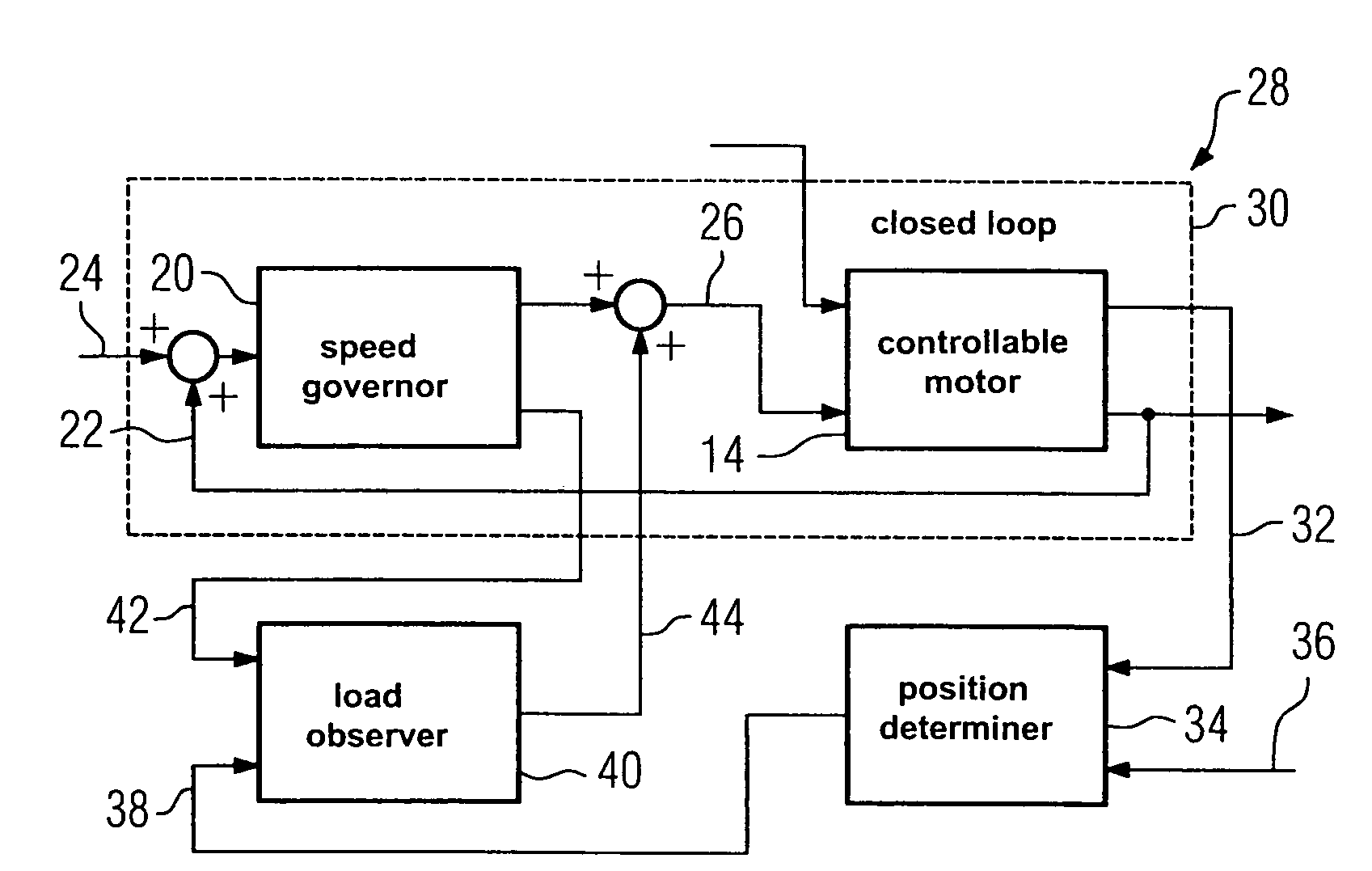
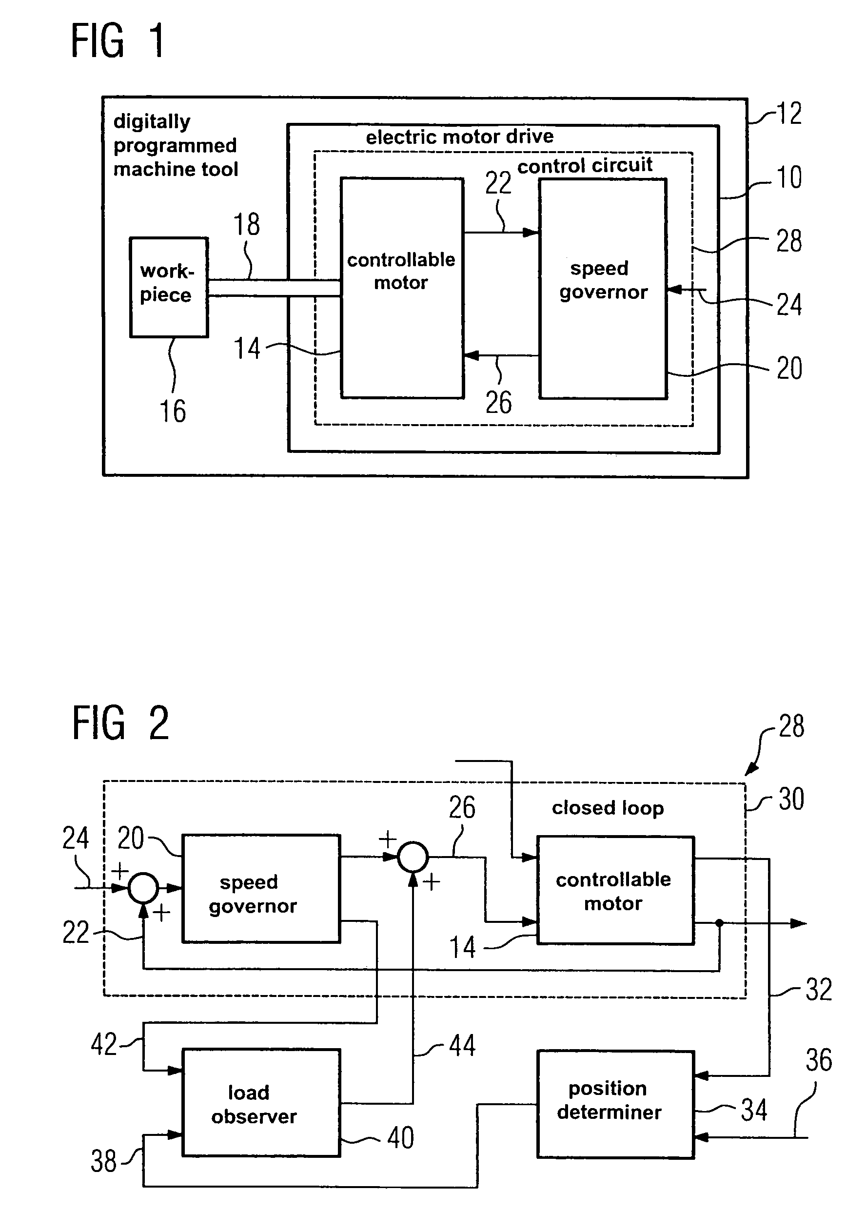
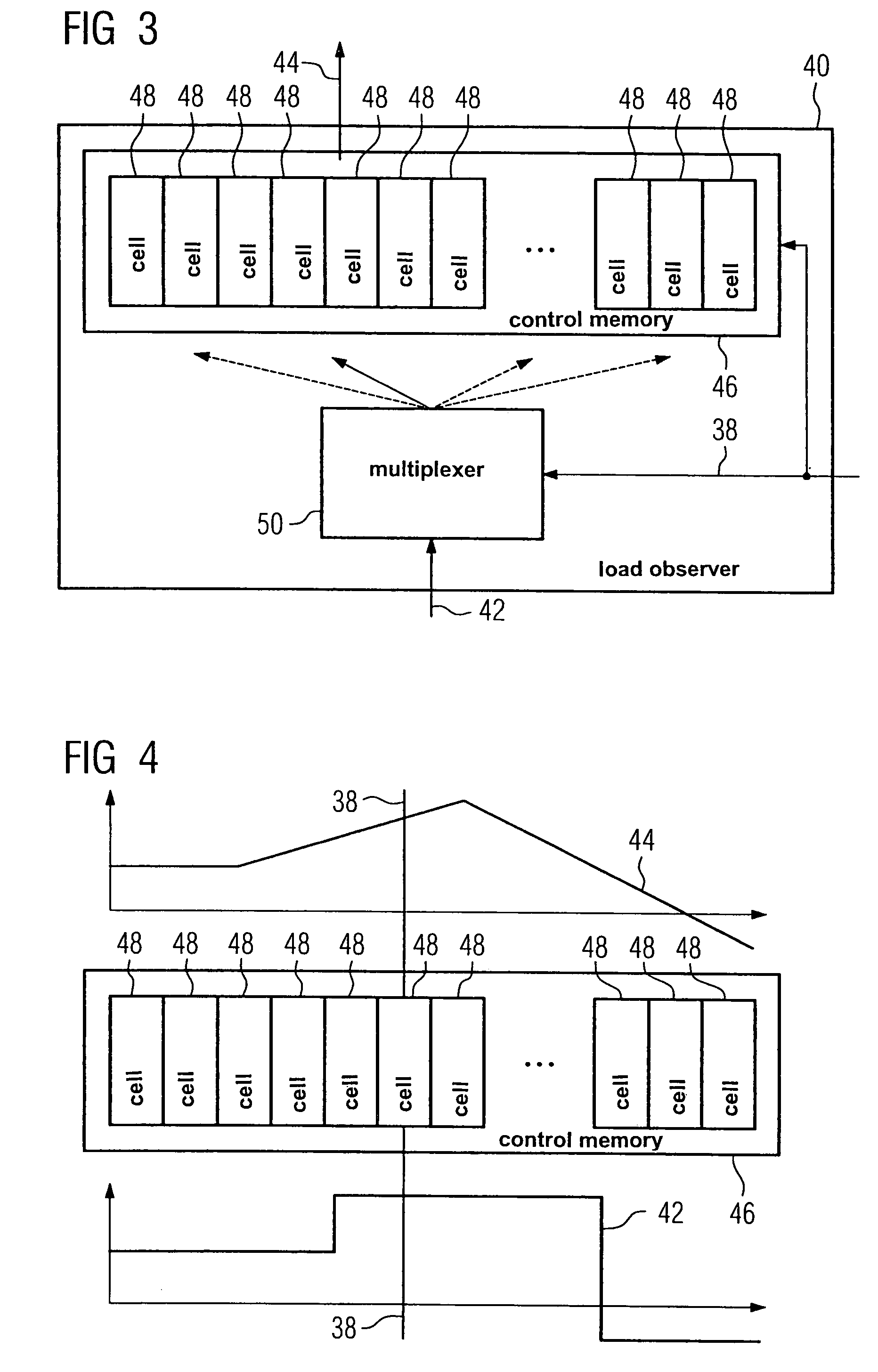
A compensation of cyclical interferences occurring during operation of motor controlled by an electrical motor drive comprising the controllable motor and a speed governor, wherein a position determiner is provided for continuously determining a position of said motor, responsive to a position signal indicative of said position of said motor and wherein a load observer responsive to a first output signal received from said position determiner and to a second output signal received from the speed governor is provided for generating a load signal indicative of an estimated load and continuously applying said load signal to an output of the speed governor.

Description

CROSS REFERENCE TO RELATED APPLICATIONS[0001]The present application claims the benefit of the provisional patent application filed on Oct. 11, 2006, and assigned application No. 60 / 851,008, and is incorporated by reference herein in its entirety.FIELD OF INVENTION[0002]The present invention relates to an electrical motor drive and to a method for operating such electrical motor drive. More particularly to such apparatus or method for use in any kind of production machinery, such as a digitally programmed machine tool, provided for adaptively compensating for a load change. The apparatus and corresponding method can therefore be termed as cyclical load observer for a compensation of cyclical interferences or cyclical load observing method for a compensation of cyclical interferences.BACKGROUND OF INVENTION[0003]Electrical motor drives are known per se. A quality of workpieces, which are by way of example machined by production machinery employing such motor drives, is clearly depend...

Claims


Application Information

Patent Timeline
Patent Type & Authority Patents(United States)
IPC IPC(8): G06F19/00G05D3/12G06F40/191
CPCH02P6/08
Inventor BIRK, GUNTHERDEMUTH, THOMAS
Owner SIEMENS AG
Learn More