Eureka AIR delivers breakthrough ideas for toughest innovation challenges, trusted by R&D personnel around the world.

Quick release device with biasing unit

a technology of a biasing unit and a quick release device, which is applied in the direction of release mechanisms, cycle equipments, axle suspensions, etc., can solve the problems of easy contamination of mud and dust by the biasing unit b>3/b>

Inactive Publication Date: 2010-03-09
CHANG CHIN CHAO
View PDF3 Cites 22 Cited by
  • Summary
  • Abstract
  • Description
  • Claims
  • Application Information

AI Technical Summary

Problems solved by technology

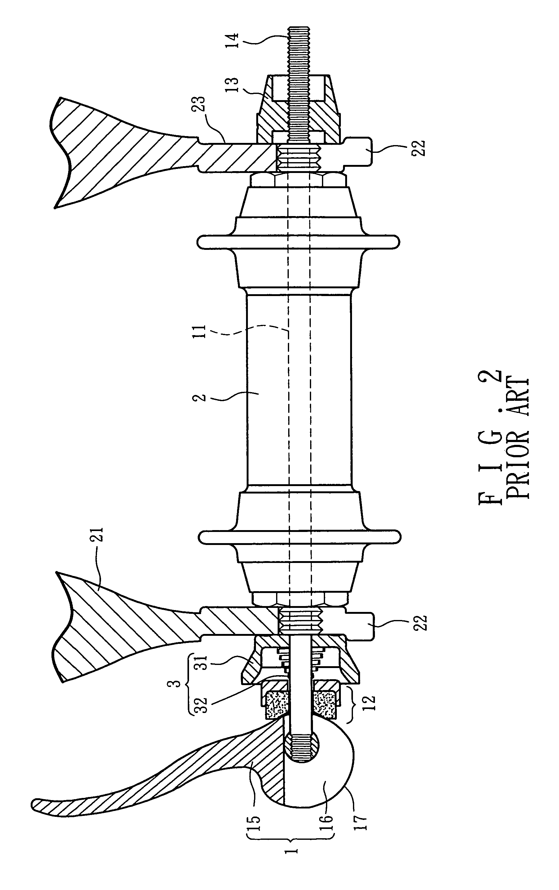
Nevertheless, the biasing unit 3 is exposed and easily contaminated by mud and dust.

Method used


Image

  • Quick release device with biasing unit
  • Quick release device with biasing unit
  • Quick release device with biasing unit

Examples


Embodiment Construction

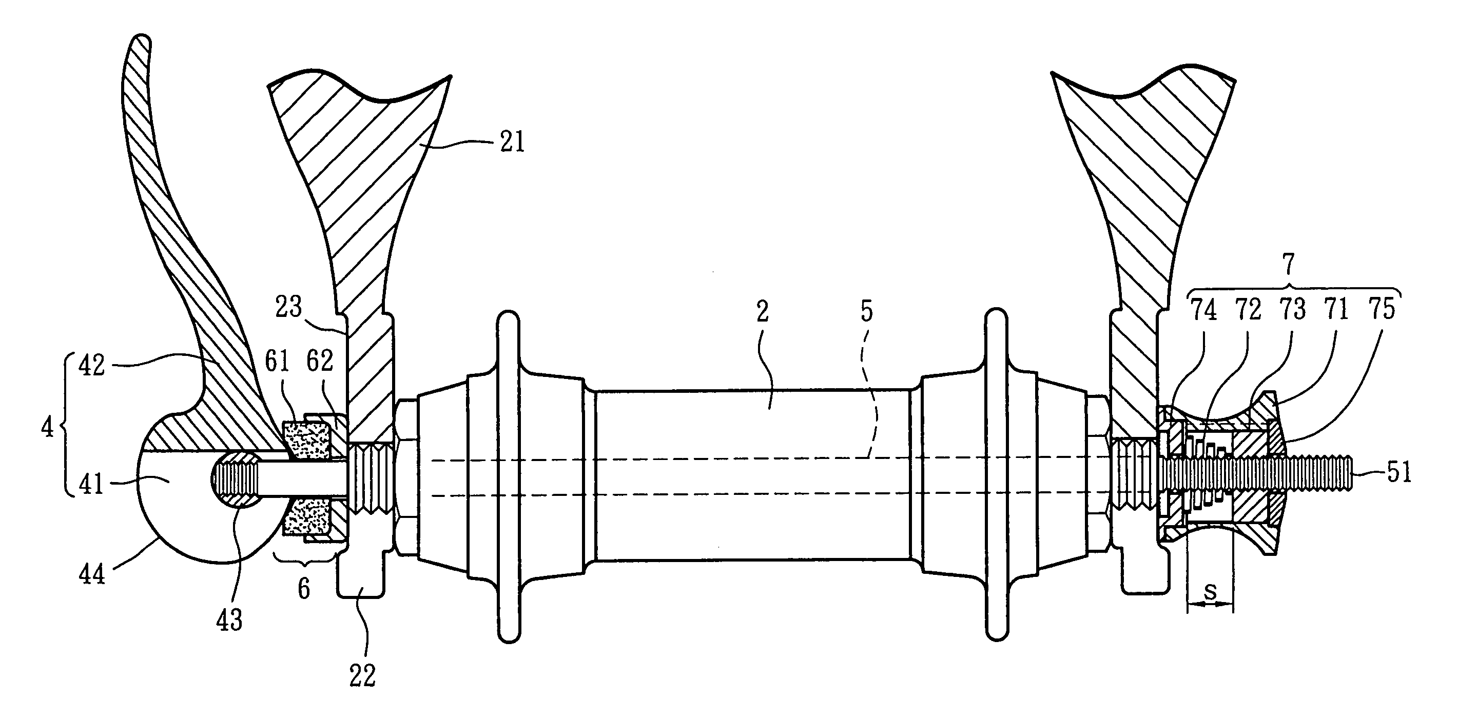
[0015]Referring to FIGS. 3 to 5, the quick release device of the present invention comprises an operation member 4 which is composed of a cam portion 41 and a lever 42 connected to the cam portion 41. The cam portion 4 includes two parallel portions and each portion includes a cam-shaped profile 44. A through hole is defined through the two parallel portions of the cam portion 41 and located eccentrically in the cam portion 41.

[0016]A cooperation unit 6 includes a pad 61 with a curved and concaved recess 611 and a cup 62 which has a receiving space 621 defined in one end thereof and the other of the cup 62 formed with a toothed surface 622. The cam portion 41 is pivotally engaged with the curved and concaved recess 611 of the pad 61. The cooperation unit 6 is located at an end of the hub 2 of a front wheel (for example). The toothed surface 622 of the cup 62 of the cooperation unit 6 is engaged with one of the two legs of the front fork.

[0017]A rod 5 has a first threaded section at ...


PUM


Abstract

A quick release device includes a cam portion and a lever connected to the cam portion, a cooperation unit with which the cam portion is pivotably engaged, a rod having a first threaded section at a first end thereof and the threaded section extending through the cooperation unit and into the cam portion and threadedly connected with a pin which transversely extends through the cam portion, a second end of the rod including a second threaded section which extends through a biasing unit and is connected with an adjustment member in the biasing unit. The biasing unit pulls rod in a direction away from the operation member. The biasing unit is a tubular member which accommodates the spring and the adjustment member therein.

Description

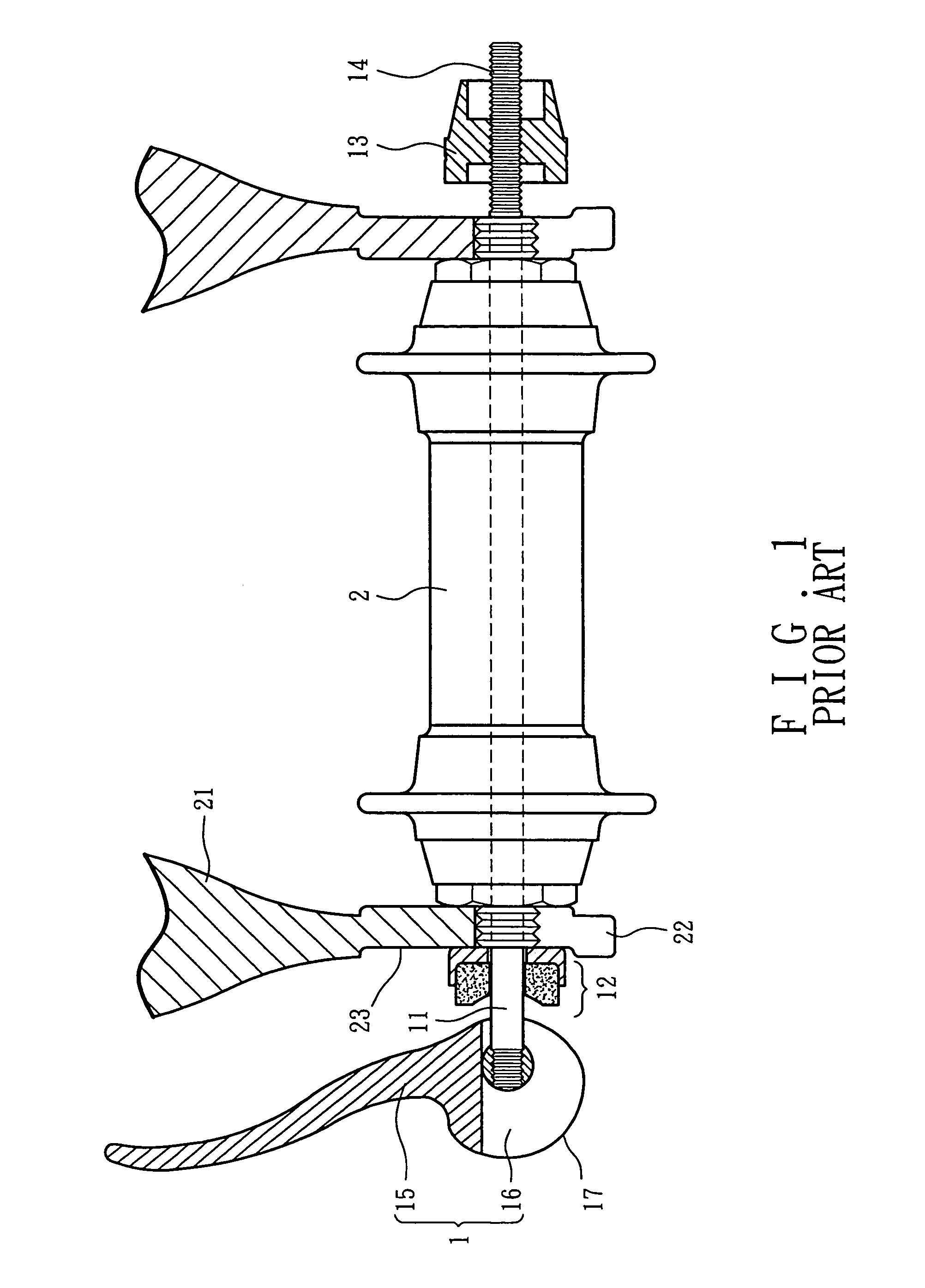
FIELD OF THE INVENTION[0001]The present invention relates to a quick release device with a biasing unit which keeps the items that to be secured from being loosened during operation of the quick release device.BACKGROUND OF THE INVENTION[0002]A conventional quick release device for connecting the axle 2 of a front wheel to the two legs 21 of front fork or for connecting the axle of a rear wheel to the chain stays is shown in FIG. 1 and generally includes an operation member 1 which is composed of a lever 15 and a cam portion 16 which includes a curved periphery 17. A rod 11 has one end connected to the cam portion 16 and the other end of the rod 11 extends through a cooperation unit 12, one of the legs 21 of the front fork, the axle 2 of the front wheel, the other leg of the front fork and is threadedly connected with a nut 13 by a threaded section 14 of the rod 11. Each leg 21 of the front fork includes a recessed area 23 defined in an outside thereof so as to receive the cooperati...

Claims


Application Information

Patent Timeline
Patent Type & Authority Patents(United States)
IPC IPC(8): B60B37/00
CPCB62K25/02B62K2206/00
Inventor CHANG, CHIN-CHAO
Owner CHANG CHIN CHAO
Why Eureka
Eureka Blog
Learn More